Kunhao Ji1, Di Lin1,2,3,*, Ian A. Davidson1, Siyi Wang1..., Joel Carpenter4, Yoshimichi Amma5, Yongmin Jung1, Massimiliano Guasoni1 and David J. Richardson1|Show fewer author(s)
1Optoelectronics Research Centre, University of Southampton, Southampton SO17 1BJ, UK
2Current address: Institute of Advanced Photonics Technology, School of Information Engineering, Guangdong University of Technology, Guangzhou 510006, China
3Current address: Guangdong Provincial Key Laboratory of Photonics Information Technology, Guangdong University of Technology, Guangzhou 510006, China
4School of Information Technology and Electrical Engineering, The University of Queensland, Brisbane, QLD 4072, Australia
Kunhao Ji, Di Lin, Ian A. Davidson, Siyi Wang, Joel Carpenter, Yoshimichi Amma, Yongmin Jung, Massimiliano Guasoni, David J. Richardson, "Controlled generation of picosecond-pulsed higher-order Poincaré sphere beams from an ytterbium-doped multicore fiber amplifier," Photonics Res. 11, 181 (2023)
Copy Citation Text
Higher-order Poincaré sphere (HOPS) beams with spatially variable polarization and phase distributions are opening up a host of unique applications in areas ranging from optical communication to microscopy. However, the flexible generation of these beams with high peak power from compact laser systems remains a challenge. Here, we demonstrate the controlled generation of HOPS beams based on coherent beam combination from an Yb-doped multicore fiber (MCF) amplifier. Using a spatial light modulator to adaptively adjust the wavefront and polarization of the signals seeded into the individual cores of the MCF various structured beams (including cylindrical vector beams and first- and second-order vortex beams) were generated with peak powers up to 14 kW for pulses.
1. INTRODUCTION
Structured light beams have recently become an attractive tool in a variety of applications, including optical communication [1], optical trapping [2,3], environmental optics [4], and super-resolution microscopy [5–7], due to their additional degrees of freedom in the shaping of polarization state, phase, and amplitude. In particular, higher-order Poincaré sphere (HOPS) beams [8] with spatially variable polarization and orbital angular momentum (OAM) states are of great interest [9–11]. The two poles of the HOPS represent the orthogonally circularly polarized vortex beams carrying OAM with opposite topological charges, while the other points on the HOPS can be represented as coherent superpositions of these, including cylindrical vector (CV) beams with spatially varying polarization states (e.g., radial and azimuthal polarization). Various methods have been developed to generate HOPS beams by incorporating appropriate spatial mode shapers either inside or outside of a laser cavity [12–28]. For instance, CV beams can be generated by using inhomogeneous birefringent optics [12–14] or by the controllable superposition of two orthogonally polarized beams [15]. OAM beams can usually be formed by conversion from fundamental Gaussian beams using an external beam-shaping element, such as a -plate (QP) [16], geometric phase plate [17], metasurface device [18,19], or spatial light modulator (SLM) [11,20,21]. Generating such beams directly from a laser cavity [22–28] tends to provide for higher power scaling and efficiency.
The generation of such beams with tunable properties in terms of wavelength, polarization, temporal shape, and topological charge has attracted considerable interest in recent years. A few approaches have been implemented to generate HOPS beams with flexible mode selection and high mode purity in solid-state lasers; however, the power scalability is limited by the power-handling performance of the optical mode-selective elements used within the cavity [21]. Alternatively, adaptive spatial beam-shaping techniques have been demonstrated in multimode and multicore fibers [29,30] based on the master oscillator power amplifier (MOPA) configuration. The adaptive beam-shaping elements are placed prior to the final power amplifier, allowing the amplified beam to be shaped into the desired beam intensity profile without exposing the beam-shaping elements to high power levels. In addition, the coherent combination of multiple parallel fiber lasers has been proposed as a promising way to achieve reconfigurable structured beams with high output powers and has been investigated both theoretically and experimentally [31–33]. Coherent beam combination (CBC) from an MCF amplifier has been demonstrated as an effective way to generate the conventional Gaussian beams when all output beamlets are locked in phase [34–36]. Recently, we demonstrated the efficient generation of structured beams by coherently combining seven individual beamlets (with narrow spectral linewidth) emitted from an Er/Yb-doped MCF amplifier. Good beam-shaping performance was achieved albeit at a moderate output power of under continuous wave operation [37]. With all uncoupled cores embedded in a single fiber, the MCF amplifier offers many advantages with respect to an array of separate fiber amplifiers, e.g., the use of a common pump beam for all cores and reduced phase drift between cores due to the shared spatial/thermal environment, leading to more compact and stable systems. Nevertheless, to the best of our knowledge, the behavior in the pulsed regime has not yet been properly investigated, where the coherence length of the light is much smaller.
In this work, we fabricated a novel six-core ytterbium (Yb)-doped MCF and employed it as the gain medium in the final power amplifier stage in a picosecond pulsed MOPA system. A flexible beam shaper based on a reflective phase-only SLM was employed to adaptively adjust the wavefront and polarization states of the multiple beamlets incident on the individual MCF cores and to achieve the desired complex beam amplitude in the far-field of the MCF output by coherently combining the amplified multiple beamlets. We experimentally demonstrated the generation of ps-pulsed HOPS beams (i.e., CV and OAM beams) with a high mode purity and a high peak power of .
Sign up for Photonics Research TOC. Get the latest issue of Photonics Research delivered right to you!Sign up now
2. METHODS
A. Yb-Doped Six-Core MCF
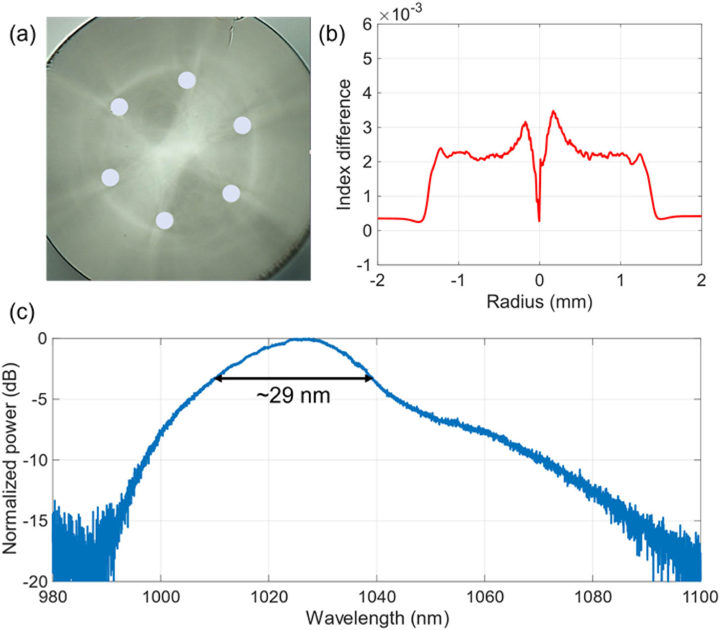
A cross-sectional microscope image of the Yb-doped six-core MCF used in this work is shown in Fig. 1(a). Starting from a flat-topped step-index Yb-doped fiber preform co-doped with aluminum (Al) and phosphorus (P) (manufactured by Fujikura Ltd.), the MCF has been fabricated in-house by the stack-and-draw technique. By adding co-dopants such as Al and P, the absorption and emission properties of the Yb ions can be efficiently controlled [38,39]. The refractive index profile was measured with a preform analyzer, and the refractive index difference between the core and the cladding was measured to be , as shown in Fig. 1(b). The MCF consists of six step-index circular cores in a hexagonal arrangement, and the core-to-core distance is μ. Each core has a diameter of 12.5 μm with a numerical aperture (NA) of ; the outer diameter of the fiber is μ. A low-index acrylate polymer coating was used to provide a double-clad fiber structure. The fiber absorption coefficient was measured to be at 975 nm, and the amplified spontaneous emission (ASE) spectrum was measured. The ASE spectrum of 1.3 m Yb-MCF had an emission peak around 1027 nm with a 3 dB bandwidth of , as shown in Fig. 1(c).
Figure 1.Yb-doped six-core MCF. (a) Microscopic image of fiber cross-section. (b) Refractive index profile of the fabricated preform. (c) ASE spectrum of the MCF.
A schematic of the experimental setup is depicted in Fig. 2. A gain-switched laser diode operating at a wavelength of 1035 nm and emitting pulses at a repetition rate of 2.95 MHz, is used as the seed, which is preamplified to an average power of . The preamplified Gaussian-shaped beam is then split into six beamlets, which are coupled into the individual cores of the Yb-MCF via a beam-shaper consisting of a reflective SLM (Holoeye PLUTO-2-NIR-149) and some polarization diversity optics, which enables independent control of the amplitude, phase, and polarization state of the seed light launched into the individual cores of the MCF. The input beam is collimated by a lens with a focal length of 40 mm and then is divided into two beams with orthogonal polarization states using a PBS. A half-wave plate placed in front of the PBS is used to control the relative power ratio between the two orthogonally linearly polarized beams, and a second half-wave plate is used to align the polarization orientations of the two beams to the SLM. The area of the SLM is divided into two halves to display the phase masks, which split each input beam into six independent Gaussian-shaped beamlets with controlled phase and amplitude. The phase mask represents a multiplex of six independent blazed gratings with the grating period determined by the relative position of the MCF cores. Another half-wave plate and a PBS are used to recombine these orthogonally polarized beams to form six individual Gaussian-shaped beamlets with user-defined polarization, amplitude, and phase in the Fourier plane of the lens, which is then coupled into the MCF.
The shaped input beam is first demagnified by a factor of 2 with a pair of lenses (focal length of 1 m and 500 mm), and then passed through an in-house-made free-space polarization-independent isolator with a clear aperture of 8 mm, which prevents any backward-propagating light from damaging the SLM. The isolator consists of two birefringent beam displacers, a Faraday rotator, and a half-wave plate, which was carefully aligned to have a negligible displacement for beams with two orthogonal polarization components at the isolator output, thus ensuring a very low polarization-dependent coupling loss to the MCF. A lens with a focal length of 19 mm is used to couple the six individual beamlets into the individual cores of the Yb-MCF. This fiber is long and was coiled with a diameter of on an aluminum cylinder to induce high excess losses for the higher-order modes so that each core could effectively act as a single-mode fiber (), ensuring that the output beam of each core maintains a Gaussian shape. Both ends of the Yb-MCF were spliced to silica coreless fiber endcaps with a length of and a diameter of μ to suppress potential parasitic lasing. The input end facet was perpendicularly cleaved for high-quality beam excitation, while the output end facet was polished with an angle of to suppress unwanted backreflection. The multimode pump beam was free-space coupled into the MCF through a dichroic mirror. The insertion loss of the beam-shaper and of the isolator was characterized by means of a passive seven-core MCF having cores arranged in a hexagonal pattern with the same core pitch distance (50 μm). The passive MCF features an extra core in the center, and each core has a mode field diameter of μ with an NA of , which is slightly different from the active fiber. Nevertheless, it can be used to assess the insertion loss of the devices. The total insertion loss of the beam-shaper and isolator (measured from the input SMF to the output facet of the passive MCF) was measured to be with some variation between the cores, which is mainly due to imperfect coupling conditions. It is worth mentioning that the beam-shaper was constructed based on a specially designed compact architecture with most of the optical components glued to the mechanics in a Mach–Zehnder interferometer configuration. The coupling efficiency of the individual beamlets into the MCF is quite stable over periods of several hours.
The output beam from the Yb-MCF amplifier was first magnified by a factor of 10 to achieve a separation of μ between the neighboring beamlets to match the lens pitch of the microlens array (MLA). The MLA has a hexagonal arrangement with a focal length of 50 mm, and it collimates the individual beamlets with a beam spot diameter of μ. Note that the use of MLA can increase the near-field filling factor of the output beamlets; hence, this significantly improves the beam-combination efficiency in a tiled-aperture configuration [35,40]. A spherical lens with a focal length of 200 mm was placed behind the MLA to achieve the CBC, thereby enabling the generation of different HOPS beams in the far-field. Afterward, the coherently combined beam is collimated and magnified using a pair of lenses, with a fraction () imaged on a CCD camera, and a replica beam from the beam splitter passed through a mode correlation filter in order to characterize the quality of the combined beam. A -plate in combination with two quarter-wave plates (QWPs) and a linear polarizer were used to form the correlation filter for the HOPS beam generation [26,37]. When the collimated combined beam passes through the correlation filter, the on-axis intensity in the far-field is proportional to the power of the beam within the target mode. The resulting correlation signal is detected by coupling the light into an SMF and measuring the corresponding coupled power. This information is fed back to the computer, and an iterative optimization process (conjugate gradient algorithm [41]) is used to adjust the complex amplitude and polarization of the seed light injected into the individual cores of the MCF via the beam shaper (see Ref. [37] for a more detailed description). The bandwidth of the feedback loop is 4 Hz, determined by the time required to allow the SLM to update the phase mask, to measure the correlation signal, and to perform the associated software-based data processing.
3. RESULTS AND DISCUSSION
A. MCF Amplifier Characterization
In a preliminary experiment, the Yb-MCF amplifier was first characterized without implementing any adaptive beam-shaping. Figure 3(a) shows the measured near-field beam intensity profile of the MCF output with a magnification. The discrepancy in the amplification of each core results from the nonuniform pump absorption and unavoidable seed power variations, as mentioned in Section 2. The differential gain among individual cores is between 0.84 and 1.46 dB at different pump powers when sequentially launching light into each core. Figure 3(b) shows the average output power of the MCF amplifier (measured before the MLA) as a function of the launched pump power. A maximum output power of was obtained with a launched pump power of , corresponding to a slope efficiency of and a gain of . The measured spectra of the seed and the output beam at the maximum output power of are shown in Fig. 3(c), with a resolution of 0.5 and 0.02 nm, respectively. The output signal had an OSNR of . The 3 dB bandwidth was measured to be , and it contains of the total pulse energy, which is nearly equivalent to that of the seed laser. The pulse duration of the seed laser was measured to be , and the temporal shape was preserved in the output laser beam, as shown in Fig. 3(d).
Figure 3.Yb-MCF amplifier characterization. (a) Measured near-field intensity distribution of the MCF output. (b) Average output power versus the launched pump power. (c) Measured spectra of the seed and of the amplified output at an average output power of [ and ]. (d) Temporal pulse shapes of the seed and the amplified output at .
B. Generation of Linearly Polarized Gaussian Beams
When the phase control is not in place, the output beam of the MCF amplifier exhibits severe distortion in the far-field, as shown in Fig. 4(a). A linear polarizer in combination with an SMF forms the spatial mode correlation filter that provides the correlation signal for the merit function. This finally results in a linearly polarized Gaussian-shaped beam within the main lobe via in-phase CBC [as illustrated in Fig. 4(b)]. Figures 4(c) and 4(d) show the corresponding measured beam intensity profiles with a seed signal of and a pump power of . Figures 4(c-1), 4(c-2) and 4(d-1), 4(d-2) show the intensity distributions when the output beams pass through a rotatable linear polarizer, which clearly indicates the linear polarization state. The polarization extinction ratio (PER) was measured to be . The 2D correlation coefficients [42] of the measured intensity profiles with respect to the theoretical intensity distributions (within the area marked with dash white lines) were calculated to be and , respectively. The measured beam combining efficiency was (defined as the ratio of the power contained within the mode region marked with dash white line with respect to the total beam power), whereas the corresponding theoretical estimation is . We envisage this discrepancy results from the optical aberrations induced by the slight misalignment of the composite elements in the beam-combining system [37]. The average output power behind the wedge (Fig. 2) was , resulting in an average output power of , with a peak power of for the combined beams (marked region). The power loss from the MCF output to the wedge is mainly due to reflections from the uncoated MLA and wedge as well as the slight mismatch between the MCF output and the MLA.
Figure 4.Generation of linearly polarized Gaussian beams. (a) Far-field beam profiles without beam shaping. (b) Simulated far-field intensity distribution when all cores are in-phase. (c), (d) Experimentally measured far-field Gaussian beam profiles at the peak power of with the orthogonal polarization states.
The generation of HOPS beams was investigated with correlation filters formed by a pair of QWPs and a QP (charge , 1), with specific orientations in combination with an SMF. The correlation filter is used to convert HOPS beams to a linearly polarized Gaussian beam, with an input-to-output relation described by [8,26] where the circular polarization basis is applied and a global phase factor is discarded, is the output state of the correlation filter, denotes the polarization state of the HOPS beam, and are the rotation angles of the QWP2 and of the -plate with respect to the orientation of the linear polarizer, respectively, and is the topological charge () with , , , and representing the left and right circular, horizontal and vertical polarization states. and determine the position of the generated target beam on the Poincaré sphere, and any HOPS beam can be obtained by suitably adjusting the rotation of the QWP2 and the -plate, as previously demonstrated in Ref. [37].
CV beams can be obtained when the fast axis of the QWP2 is aligned with the horizontal axis (), including the radially polarized beam () and the azimuthally polarized beam (). Figure 5(a) shows the calculated intensity profile of coherently combined beams when the polarization state of each core is aligned with radial orientation (blue arrow) and azimuthal orientation (yellow arrow), as illustrated in Fig. 5(b), resulting in a radially polarized beam and an azimuthally polarized beam, respectively. Figures 5(c) and 5(d) show the measured beam intensity profiles for the coherently combined radially polarized beam and azimuthally polarized beam, respectively, exhibiting a pronounced doughnut shape. The measured average output power within the white circle was and , corresponding to a beam combining efficiency of and and a peak power of and for radial and azimuthal polarization, respectively. The theoretical combining efficiency of the CV beam is ; note this is higher than that of the fundamental Gaussian beam, which can be attributed to a greater intensity overlap between the combined CV beams and the input beamlet array. The polarization states of the combined beams were confirmed by passing the beams through a rotatable linear polarizer. As expected [see Figs. 5(c-1)–5(c-4) and 5(d-1)–5(d-4)], in the case of the radially (azimuthally) polarized beam, we systematically observed a two-lobe beam pattern that was parallel (orthogonal) to the transmission axis of the rotatable linear polarizer. The 2D correlation coefficients of the measured intensity profiles with respect to the theoretical intensity distribution (within the area of the doughnut-shaped beam) were and for the radially and azimuthally polarized beams, respectively. The slight beam distortion of the doughnut-shaped intensity profiles is most likely due to the nonuniform power distribution of the individual beamlets. The mode extinction ratio was measured to be by the vector mode decomposition approach described in Refs. [43,44].
Figure 5.Generation of CV beams. (a) Simulated far-field intensity distribution when the polarization orientations of the six beamlets are set as per the arrow directions in (b). (c) Experimentally measured radially polarized output beam profile with a peak power of , and the two-lobe patterns when the beam is passed through a linear polarizer at different orientations (white arrows). (d) Experimentally measured azimuthally polarized beam profile (at ) and the two-lobe patterns after passing through the linear polarizer.
Furthermore, we successfully generated the first-order OAM beams () with opposite handedness of helical phase front as shown in Figs. 6(a) and (d). According to Eqs. (1) and (2), a left circularly polarized OAM beam with left handedness can be obtained when the fast axis of the QWP2 is rotated at with respect to the horizontal axis. The QWP1 with the fast axis rotated at was used to convert this beam to a horizontally polarized OAM beam. A right-handedness OAM beam in the vertical polarization state can be generated with the fast axes of the QWP1 and QPW2 both rotated at 45°. The polarization states of the OAM beams were confirmed by passing the beams through a rotatable linear polarizer, as is shown in Figs. 6(a-1), 6(a-2) and 6(d-1), 6(d-2), and the PER was measured to and , respectively. The helicity was also analyzed by interfering the beam with a reference spherical wavefront beam, and the characteristic spiral fringes with the opposite rotation directions, as shown in Figs. 6(b) and 6(e), indicate beams with a topological charge of , respectively. Figures 6(c) and 6(f) plot the 1D intensity profiles across the beam center [marked with the red dashed line in Figs. 6(a) and 6(d)]. The experimental 1D intensity profiles were fitted by an incoherent superposition of the mode and the OAM mode. It turns out that the mode accounts for only of the total power in these two beams, which proves the high modal purity of the generated OAM modes. In addition, the 2D correlation coefficients of the measured intensity profiles with respect to the theoretical intensity distribution [Fig. 5(a)] were . The combining efficiency of the two OAM beams was [Fig. 6(a)] and [Fig. 6(d)], respectively, resulting in an output power of with a peak power of for the combined OAM beams.
Figure 6.Generated OAM beams (first order). (a), (d) Experimentally measured output beam profiles with a peak power of and the topological charge of , respectively, as well as the corresponding intensity distributions after the beam was passed through a rotatable linear polarizer. (b), (e) Measured spiral interference fringes for the generated OAM beams shown in (a) and (d). (c), (f) 1D intensity profiles across the beam center fitted with an incoherent superposition of the mode and the OAM mode.
Finally, we generated the second-order OAM beams () by setting an appropriate correlation filter using a QP with a charge of . In this case, the relative phase of the th beamlet is set to be , as shown in Fig. 7(b), which corresponds to petal-like intensity distribution, as shown in Fig. 7(a). It is worth noting that the petal-like intensity profile is due to the large relative phase () among adjacent cores. By smoothing the relative phase with a large number of cores, a doughnut-shaped beam could be formed. Figures 7(c) and 7(d) show the measured intensity profiles for the orthogonally linearly polarized OAM beams generated in the far-field, which are close to the theoretical calculation, indicating that the phases and polarizations of the individual beamlets were well controlled. The PER was measured to be . Figures 7(e) and 7(f) show the interference patterns of the combined beams with a reference spherical wavefront beam, confirming that the beams have a helical phase front with a topological charge of , respectively. The correlation coefficients of the measured intensity profiles with respect to the theoretical intensity distribution were . The discrepancy can be attributed to the slight power difference and residual phase shift between the individual beamlets. The average power of the combined beams within the white circle, as shown in Figs. 7(c) and 7(d), was with a peak power of , which corresponds to a combining efficiency of with respect to a theoretical value of 78%. It is worth mentioning that the coherently combined beams were stable and repeatable in the laboratory environment. The system typically took to achieve the target beams in our experiments once the correlation filter is properly set and well aligned. Once the optimization process has completed, the generated beam could be well-preserved for at least 10 min with a fixed phase mask on the SLM. However, we observed some level of slow optical/mechanical drift over time, and we had to periodically readjust/realign certain mounts to maintain good optical alignment every few tens of minutes.
Figure 7.Generation of OAM beams (second order). (a) Simulated far-field distribution when the relative phase of the six beamlets is set to the value given in (b). (c), (d) Experimentally measured beam profiles with a peak power of and the topological charge of , respectively, as well as the corresponding intensity distributions after passing through a rotatable linear polarizer. (e), (f) Measured spiral interference fringes for the generated OAM beams shown in (c) and (d).
In order to understand the difference between the experimental results and theoretical calculations, we numerically analyzed various factors affecting the quality of the coherently combined beams. First, the alignment and collimation condition in the CBC setup determine the beam-combining efficiency. Figure 8(a) shows the theoretical combining efficiency of the first-order OAM beams when each beamlet is composed of in-phase and modes with variable power weight . The combining efficiency was plotted as a function of the defocus of the MLA (, where is the distance between the MLA and the beam waist in the near-field of the MCF output, and is the focal length of the MLA). The divergent or convergent beamlets in a tiled-aperture arrangement can result in increased electric field components having higher spatial frequencies in the far-field [37] and then leading to a reduced combining efficiency in the central target beams. The combining efficiency will decrease by when the defocus is , and each beamlet is mainly in the mode (). The optimal combination is achieved with a defocus of , resulting from the interaction of defocus and non-negligible diffraction loss when the beam diameter of each beamlet is close to the clear aperture of the microlens. Figure 8(b) shows the combining efficiency of the combined beams with different MLA shifts (, where is the shift of the MLA with respect to the optical axis, and is the clear aperture of the MLA), showing that the efficiency decreases by with an MLA shift of 0.2. Second, the power distribution uniformity of the beamlets determines the spatial shape of the combined beams. When each beamlet has a different power distribution from the others, the OAM beams in the far-field will deviate from an ideal doughnut/petal shape, whereas the Gaussian-shape beam can be relatively well preserved, as shown in Fig. 8(d), respectively. The variation of the beam-combining efficiency (calculated as the power ratio within the white dashed circle) was calculated when the relative power in the selected beamlets is different (1c: 1 beamlet has a different power from the other five beamlets; 2c: two nonadjacent beamlets have the same power but different from the other four beamlets; 3c: three nonadjacent beamlets have the same power but different from the residual beamlets), as shown in Fig. 8(c). The beam-combining efficiency is quite stable even when the mode shape is fully distorted, and the variation is less than 10%, 5%, and 1% for the Gaussian beam, the first- and second-order OAM beam, respectively. These analyses support our experimental results that the slightly distorted OAM beam shape arises from the nonuniform power distribution in the MCF beamlets, whereas the lower combining efficiency is mainly related to the misalignment and collimation condition in the CBC setup.
Figure 8.Numerical analysis on the factors affecting the combining efficiency and far-field beam shape. (a) Calculated combining efficiency of the first-order OAM as a function of MLA defocus with different mode composition (weight of mode) of the MCF output. (b) Combining efficiency of the combined Gaussian and OAM beams with different MLA shifts in the CBC setup. (c) Combining efficiency of the combined beams with different power distributions of the MCF beamlets. (d) Near-field and far-field intensity profiles under different power distributions [A–D shown in (c)].
We have demonstrated the controllable generation of ps-pulsed HOPS beams from a coherently combined six-core Yb-doped MCF amplifier. With the SLM offering adaptive wavefront shaping and polarization control on the seed light to the MCF amplifier, the complex amplitude of the amplified signal was fully controlled, enabling various spatial modes to be obtained in the far-field. The linearly polarized Gaussian beams, CV beams, and linearly polarized first- and second-order OAM beams were efficiently generated with a high mode purity. The generated HOPS beams obtained an average output power of with a peak power of and a pulse duration of . The MCF architecture offers a much simpler, more scalable, and more stable beam-shaping procedure compared with other CBC techniques based on multiple independent fiber amplifiers. Increasing the core count would allow for the generation of OAM beams with much higher-order topological charge. The capability to flexibly generate various spatial modes with high peak powers should provide advantages in many applications in optical communication, laser material processing, and biomedical imaging.
Kunhao Ji, Di Lin, Ian A. Davidson, Siyi Wang, Joel Carpenter, Yoshimichi Amma, Yongmin Jung, Massimiliano Guasoni, David J. Richardson, "Controlled generation of picosecond-pulsed higher-order Poincaré sphere beams from an ytterbium-doped multicore fiber amplifier," Photonics Res. 11, 181 (2023)