
Hong Cheng, Qiyang Zhang, Chuan Shen, Li Wang, Xinyu Xiang. Dual-Camera Phase Retrieval Based on Registration Restoration[J]. Acta Optica Sinica, 2021, 41(12): 1210002
- Acta Optica Sinica
- Vol. 41, Issue 12, 1210002 (2021)
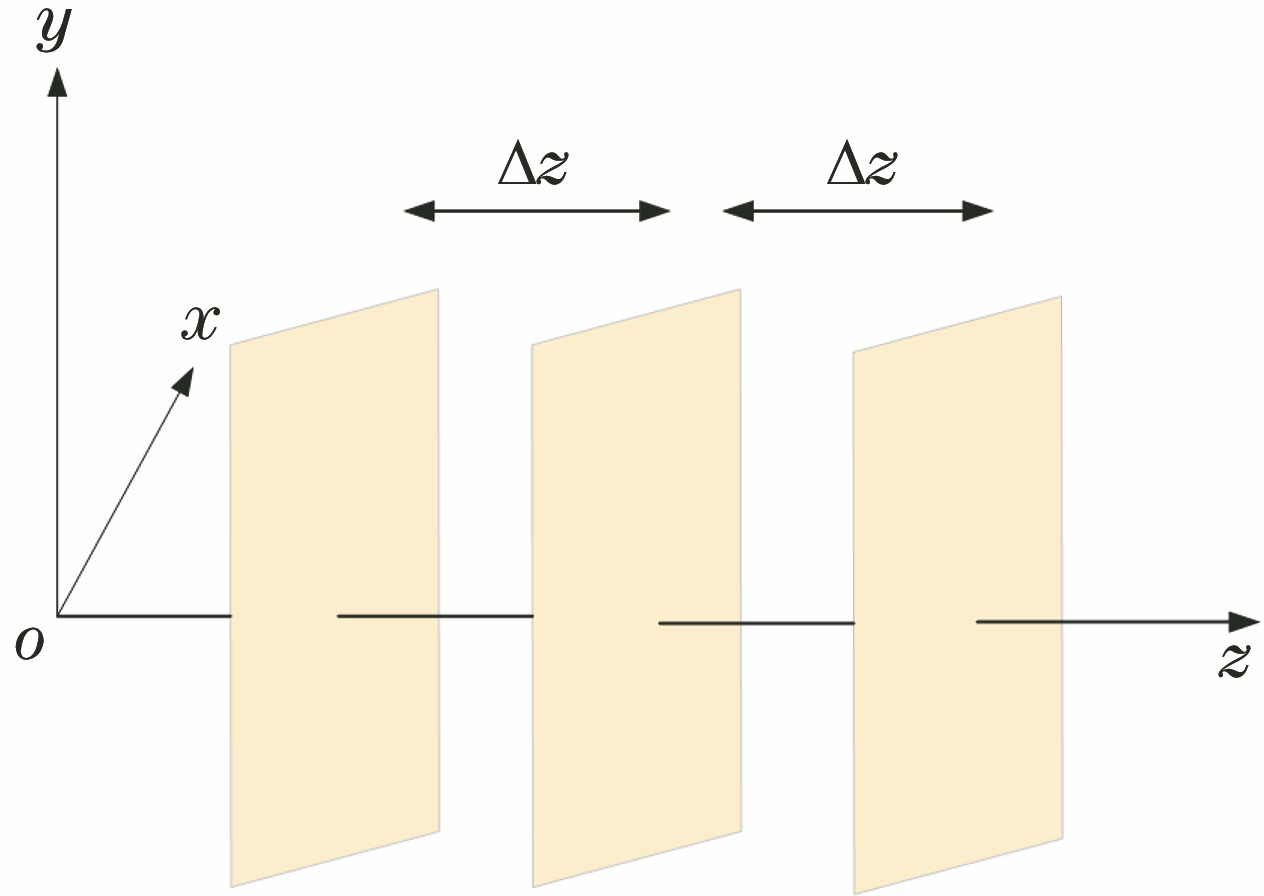
Fig. 1. Schematic of light intensity change
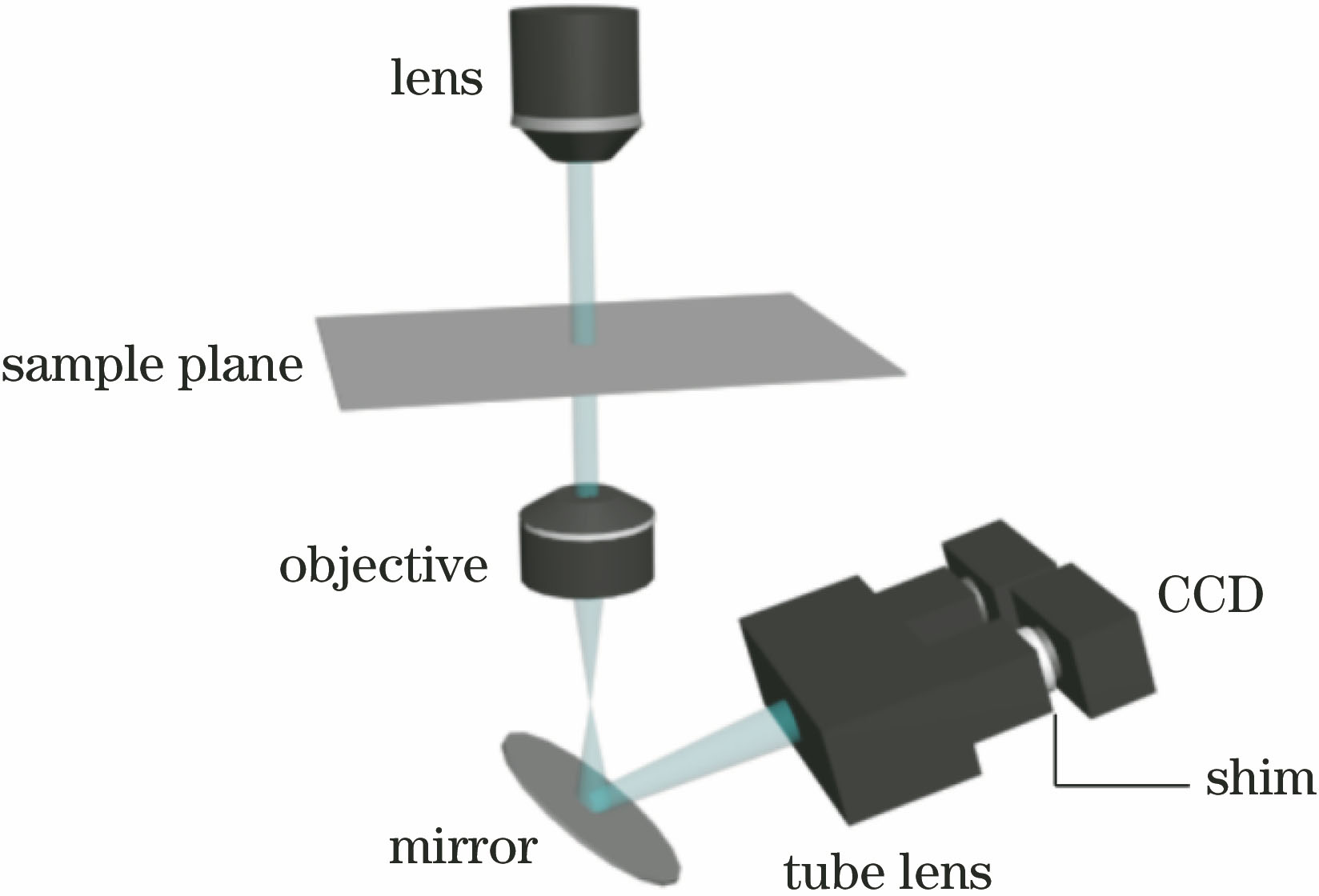
Fig. 2. Light path of microscope
Fig. 3. Translation and rotation between captured images
Fig. 4. Registration flow diagram
Fig. 5. Identifying areas to be repaired
Fig. 6. Schematic of Criminisi algorithm
Fig. 7. Flow chart of proposed algorithm
Fig. 8. Phase retrieval images without over-registration restoration. (a) Initial phase; (b) over-focus image; (c) under-focus image; (d) over-focus image after translation and rotation; (e) focus intensity image; (f) phase result of the retrieval image solved directly without any processing
Fig. 9. Phase retrieval images after registration restoration. (a) Under-focus image; (b) over-focus image to be repaired; (c) image repaired by the method in Ref. [6]; (d) image repaired by the proposed method; (e) focusing intensity obtained by the method in Ref. [6]; (f) focusing intensity obtained by the proposed method; (g) phase result retrieved by the method in Ref. [6]; (h) phase result retrieved by the proposed method
Fig. 10. Experimental device of dual-camera dynamic phase imaging system
Fig. 11. Defocus images acquired simultaneously. (a) Under-focus image; (b) over-focus image
Fig. 12. Experimental results of microlens array. (a) Under-focus image to be repaired; (b) image restored by the method in Ref. [6]; (c) image restored by the proposed method; (d) phase result retrieved by the method in Ref. [6]; (e) phase result retrieved by the proposed method
Fig. 13. Experimental results of microlens array
|
Table 1. Comparison of correlation coefficient and root mean square error under different methods


Set citation alerts for the article
Please enter your email address

© Copyright 2018-2021 | Chinese Laser Press. All Rights Reserved 沪ICP备15018463号-20