• Chinese Journal of Lasers
  • Vol. 50, Issue 12, 1202106 (2023)
Hengquan Zhang1, Xiaohui Zhou2、3, Lianfeng Wei1, Chao Sun1, Shaojun Long1, Fuyun Liu2、3, Caiwang Tan2、3、*, and Xiaoguo Song2、3
Author Affiliations
  • 1Fourth Institute of Nuclear Power Institute of China, Chengdu 610213, Sichuan, China
  • 2Shandong Institute of Shipbuilding Technology, Weihai 264209, Shandong, China
  • 3Shandong Key Laboratory of Special Welding Technology, Harbin Institute of Technology at Weihai, Weihai 264209, Shandong, China
  • show less
    DOI: 10.3788/CJL221065 Cite this Article Set citation alerts
    Hengquan Zhang, Xiaohui Zhou, Lianfeng Wei, Chao Sun, Shaojun Long, Fuyun Liu, Caiwang Tan, Xiaoguo Song. Microstructure Evolution and Mechanical Properties of 316L Joints Welded by Local Dry Underwater Laser with Double Layer Drainage[J]. Chinese Journal of Lasers, 2023, 50(12): 1202106 Copy Citation Text show less
    Welding experimental set-up and schematic of welding process. (a) Photo of welding experimental set-up; (b) underwater local dry device and schematic of welding process
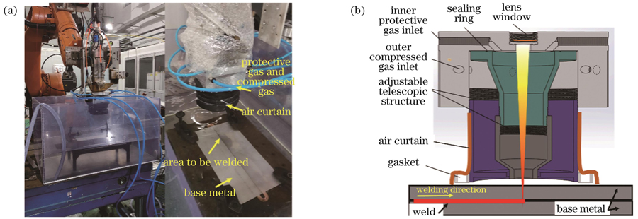
    Fig. 1. Welding experimental set-up and schematic of welding process. (a) Photo of welding experimental set-up; (b) underwater local dry device and schematic of welding process
    Schematic of sampling and sample dimension. (a) Schematic of sampling; (b) dimensions of metallographic and tensile samples
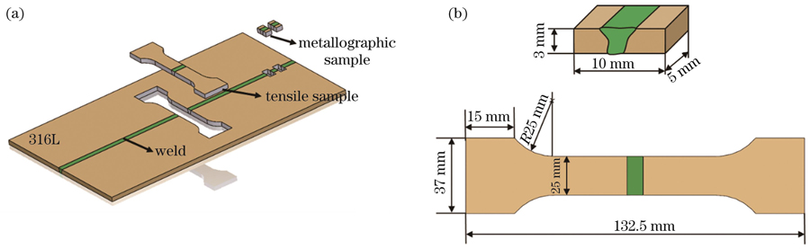
    Fig. 2. Schematic of sampling and sample dimension. (a) Schematic of sampling; (b) dimensions of metallographic and tensile samples
    Forming of 316L stainless steel laser weld surfaces under different parameters
    Fig. 3. Forming of 316L stainless steel laser weld surfaces under different parameters
    Cross-sectional morphologies of welds under different parameters
    Fig. 4. Cross-sectional morphologies of welds under different parameters
    Characters of weld cross-sectional morphology under different parameters
    Fig. 5. Characters of weld cross-sectional morphology under different parameters
    Equilibrium phase diagram of weld and Schaeffler diagram. (a) Equilibrium phase diagram of weld; (b) Schaeffler diagram[13]
    Fig. 6. Equilibrium phase diagram of weld and Schaeffler diagram. (a) Equilibrium phase diagram of weld; (b) Schaeffler diagram[13]
    Microstructures of BM and weld under different parameters
    Fig. 7. Microstructures of BM and weld under different parameters
    Welded joint samples after tensile fracture
    Fig. 8. Welded joint samples after tensile fracture
    Tensile curves of welded joint samples. (a) Joint samples welded at different drainage air pressures; (b) joint samples welded at different water depths
    Fig. 9. Tensile curves of welded joint samples. (a) Joint samples welded at different drainage air pressures; (b) joint samples welded at different water depths
    Macro-fracture surfaces of tensile samples
    Fig. 10. Macro-fracture surfaces of tensile samples
    Micro-morphologies of tensile fracture surfaces
    Fig. 11. Micro-morphologies of tensile fracture surfaces
    Tensile fracture path of welded joints
    Fig. 12. Tensile fracture path of welded joints
    ElementMass fraction /%
    C0.018
    Cr16.82
    Ni9.73
    Si0.274
    Mo2.75
    Mn1.5
    FeBal.
    Table 1. Chemical compositions of base material (BS)
    ParameterValue
    Drainage air pressure /MPa0.3
    0.4
    0.5
    Water depth /mm0
    15
    25
    35
    Table 2. Experimental parameters used during underwater laser welding process
    Welding conditionDendrite width /μmDendrite length /μm
    On land65.9142.6
    0.3 MPa45.6153.8
    0.5 MPa37.1383.3
    25 mm37.1383.3
    35 mm26.5413.7
    Table 3. Measured grain size
    Hengquan Zhang, Xiaohui Zhou, Lianfeng Wei, Chao Sun, Shaojun Long, Fuyun Liu, Caiwang Tan, Xiaoguo Song. Microstructure Evolution and Mechanical Properties of 316L Joints Welded by Local Dry Underwater Laser with Double Layer Drainage[J]. Chinese Journal of Lasers, 2023, 50(12): 1202106
    Download Citation