• Laser & Optoelectronics Progress
  • Vol. 57, Issue 23, 231409 (2020)
Kezhao Zhang1、2、*, Chaowei He1, Yuyang Lin1, Chunyan Yan1, Ke Yang1, and Yefeng Bao1
Author Affiliations
  • 1College of Mechanical and Electronic Engineering, Hohai University, Changzhou, Jiangsu 213022, China
  • 2State Key Lab of Advanced Welding and Joining, Harbin Institute of Technology, Harbin, Heilongjiang 150001, China
  • show less
    DOI: 10.3788/LOP57.231409 Cite this Article Set citation alerts
    Kezhao Zhang, Chaowei He, Yuyang Lin, Chunyan Yan, Ke Yang, Yefeng Bao. Microstructures and Mechanical Properties of Laser Cladding Repaired 5A06 Alloys[J]. Laser & Optoelectronics Progress, 2020, 57(23): 231409 Copy Citation Text show less
    Schematic of laser cladding repairing process and sampling position of tensile specimen. (a) Laser cladding repairing process; (b) sampling position of tensile specimen
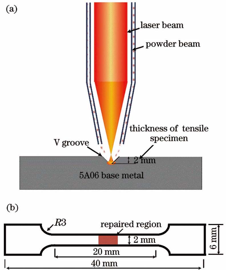
    Fig. 1. Schematic of laser cladding repairing process and sampling position of tensile specimen. (a) Laser cladding repairing process; (b) sampling position of tensile specimen
    Microstructure of base metal. (a) Microstructural characteristics; (b) EDS analysis of strengthening phase
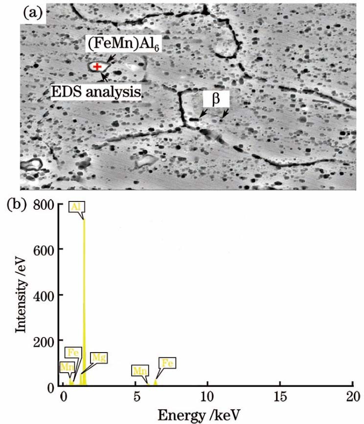
    Fig. 2. Microstructure of base metal. (a) Microstructural characteristics; (b) EDS analysis of strengthening phase
    Morphology of AlSi10Mg powder. (a) Overall morphology; (b) magnified morphology
    Fig. 3. Morphology of AlSi10Mg powder. (a) Overall morphology; (b) magnified morphology
    Influence of parameters on microstructures of heat affected zone. (a) Base metal; (b) P1; (c) P2; (d) P3
    Fig. 4. Influence of parameters on microstructures of heat affected zone. (a) Base metal; (b) P1; (c) P2; (d) P3
    Grain morphology in repaired zone. (a) Near heat affected zone; (b) within transition zone; (c) within cladding layer
    Fig. 5. Grain morphology in repaired zone. (a) Near heat affected zone; (b) within transition zone; (c) within cladding layer
    Microstructures of repaired zones under different parameter combinations. (a) P1; (b) P2; (c) P3
    Fig. 6. Microstructures of repaired zones under different parameter combinations. (a) P1; (b) P2; (c) P3
    Distributions of Al and Si elements in repaired zone. (a) Morphology of repaired zone; (b) distribution of Al element; (c) distribution of Si element
    Fig. 7. Distributions of Al and Si elements in repaired zone. (a) Morphology of repaired zone; (b) distribution of Al element; (c) distribution of Si element
    Al-Si binary phase diagram [25]
    Fig. 8. Al-Si binary phase diagram [25]
    Defects in repaired zones under different parameter combinations. (a) P1; (b) P2; (c) P3
    Fig. 9. Defects in repaired zones under different parameter combinations. (a) P1; (b) P2; (c) P3
    Morphologies of base metal and tensile fracture repaired samples under different parameter combinations. (a) Base metal; (b) P1; (c) P2; (d) P3
    Fig. 10. Morphologies of base metal and tensile fracture repaired samples under different parameter combinations. (a) Base metal; (b) P1; (c) P2; (d) P3
    Parameter combination No.Laser power /WScanning speed /(mm·s-1)Gas flow rate /(L·min-1)Powder feeding speed /(g·min-1)
    P16006102.5
    P210006104.9
    P3140016104.9
    Table 1. Parameters used in laser cladding repairing process
    MaterialAlSiMgFeTiZnMn
    5A06Bal.--6.20.20.1--0.6
    AlSi10MgBal.10.061.93--0.411.710.54
    Table 2. Chemical compositions of base metal and filler powder(mass fraction,%)
    ConditionStrength /MPaElongation /%
    Base metal334.620.3
    P199.41.8
    P276.91.3
    P3212.62.8
    Table 3. Tensile properties of 5A06 base metal and repaired samples at room temperature
    Kezhao Zhang, Chaowei He, Yuyang Lin, Chunyan Yan, Ke Yang, Yefeng Bao. Microstructures and Mechanical Properties of Laser Cladding Repaired 5A06 Alloys[J]. Laser & Optoelectronics Progress, 2020, 57(23): 231409
    Download Citation