Abstract
In this Letter, a 116-actuator deformable mirror (DM) was used to correct the wavefront distortion in a 10.7 J, 10 Hz neodymium-doped yttrium aluminum garnet (Nd:YAG) slab amplifier. By applying a pump-light homogenizer to transform the 3 × 1 near-field beam array into an integrated beam, the beam quality was greatly improved from 5.54 times diffraction limit (TDL) to 1.57 TDL after being corrected by the DM. To the best of our knowledge, this is the first investigation on beam quality control of an arrayed near-field beam in high-energy diode-pumped solid-state lasers.High-energy diode-pumped solid-state lasers (DPSSLs) with high beam quality are important sources for a wide range of applications such as laser–plasma interactions, hard X-ray generation, and inertial fusion energy (IFE). The joule-class nanosecond laser has been generated from slab amplifiers in an active-mirror configuration, which has the advantages of high-energy extraction efficiency, outstanding thermal management, and an output with a symmetrical beam profile[1–5]. In 2017, an output energy of 12.2 J at 10 Hz was realized by our group from a neodymium-doped yttrium aluminum garnet (Nd:YAG) slab amplifier based on a distributed active-mirror amplifier chain[6]. It is notable that the output beam had a near-field beam profile of three rows and one column (i.e., a array), the same as that of the laser diode (LD) array, since no shaping optics was applied to the pump light to increase the optical efficiency[6]. Meanwhile, the output beam had bad beam quality that needs further improvement. Actually, such arrayed near-field beams with bad beam quality have been reported to exist in other laser systems, in which the near-field intensity distributions are determined by the pump intensity distributions[7,8]. In a 7 kW direct-liquid-cooled side-pumped Nd:YAG multi-disk laser resonator, the near-field beam was in a array, the same as the pump intensity distribution. The root-mean-square (RMS) value of the wavefront was 0.926 μm, which indicated bad beam quality[7]. Therefore, high beam quality is a big challenge in a high-energy laser with an arrayed near-field beam.
Deformable mirrors (DMs), which have been effective in improving the beam quality of high-power lasers[9–11] and high-energy lasers[12], could be used to correct the wavefront distortion and improve the beam quality. Note that the incident beams on the DMs are integrated beams in the reported literatures[10,12], not the beam arrays. Therefore, it is necessary to investigate the beam quality control of a beam array by a DM and achieve the best beam quality.
In this Letter, a high beam quality high-energy laser is achieved by a Nd:YAG slab amplifier with an adaptive optics (AO) configuration. An investigation on beam quality control of a high-energy laser with an arrayed near-field beam was made in the simulation and experiment. In the simulation, the correction ability of a DM on different beam arrays and the beam quality after correction were investigated. Diffraction-limited beam quality could be reached with a beam array (i.e., an integrated beam). It indicates that by utilizing pump homogenization to get an integrated near-field beam and an AO configuration to achieve the wavefront correction, the beam quality of a high-energy laser could be improved. Experimental validation was performed on the Nd:YAG slab amplifier[6]. By applying a pump-light homogenizer to transform the pump beam from a array into an integrated beam, the beam quality was greatly improved from 5.54 times diffraction limit (TDL) to 1.57 TDL after being corrected by the 116-actuator piezoelectric (PZT) DM. To the best of our knowledge, this is the first investigation on beam quality improvement of an arrayed near-field beam in the high-energy DPSSL.
Sign up for Chinese Optics Letters TOC. Get the latest issue of Chinese Optics Letters delivered right to you!Sign up now
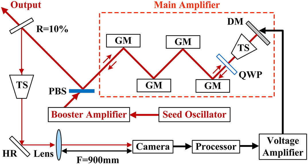
A schematic of the Nd:YAG slab amplifier[6] with an AO configuration is shown in Fig. 1. The design details for the seed oscillator, booster amplifier, and main amplifier have been reported previously[6]. The laser went through a double pass in the main amplifier. The size of the output beam from the booster amplifier was . A telescope (TS) with a magnification of two was used to expand the beam size on a lab-made PZT DM[9,10]. A beam splitter with a reflectivity of 10% was used to transmit the main energy and reflect a probing beam that was condensed by a TS for adaptive aberration control. An AO configuration was used to correct the wavefront distortion. A far-field laser beam was imaged on the focal plane of a lens with a focal length of 900 mm and was measured by a beam-profiling camera (SP300 of Ophir Photonics). A near-field laser beam was measured at the position of the lens. The far-field beam diameter was set as the feedback signal to the processor to conduct a closed-loop correction.

Figure 1.Schematic of the Nd:YAG slab amplifier with an AO configuration. HR, high reflection mirror; PBS, polarization beam splitter; GM, gain module; QWP, quarter-wave plate; TS, telescope.
A common metric of the beam quality in high-energy lasers is the horizontal beam quality (HBQ), which is defined as the ratio of the far-field divergence angle of the measured beam to that of the ideal beam for a given power-in-the-bucket (PIB)[13,14]. An ideal square top-hat beam has 81% of the entire energy encircled by the first minimum, which is set to be the PIB, and a far-field divergence angle is , where is the full width of the near-field beam, and is the laser wavelength. Therefore, , where is the diameter of the far-field beam, and is the focal length of the lens. Both and are calculated with the PIB of 81%.
In order to achieve high pump power, a large-size LD stack is necessary for the DPSSL. However, a large-size LD stack is difficult to be manufactured into an integrated stack and has to be divided into an LD array, since the temperature distribution is inhomogeneous across the integrated stack despite the use of a micro-channel heat sink, which would broaden the emission spectrum and lower the absorption efficiency[15,16]. Therefore, a LD array with a size of and a peak power of 45.1 kW was used as the pump source in the main amplifier [see Ref. [6] and Fig. 2(a)]. Since no shaping optics was applied to the gain module to increase the efficiency [see Ref. [6] and Fig. 2(b)], the pump intensity in a Nd:YAG slab was distributed in a array as well [Fig. 2(c)]. An output energy of 12.2 J was achieved, corresponding to an optical efficiency of 20.6%.
Figure 2.(a) LD array. (b) Gain module without shaping optics. (c) Simulation pump intensity distribution in a Nd:YAG slab without shaping optics. The red rectangle represents the laser beam in a Nd:YAG slab.
The experimental results of beam quality with the pump-beam array are shown in Fig. 3. The near-field beam was distributed in a array [see Ref. [6] and Fig. 3(a)]. Therefore, multiple-slit diffraction was introduced, which would degenerate the beam quality. Moreover, strong thermal effects distorted the wavefront and resulted in a weak and dispersed far-field beam [Fig. 3(c)]. The sizes of the near-field beam and the far-field beam were 4.09 and 5.10 mm, respectively, leading to an HBQ of 10.89 TDL, which needed improvement.
In order to improve the beam quality, a continuous-surface 116-actuator hexagonally distributed PZT DM[9,10] was used to correct the wavefront distortion. The stochastic parallel gradient descent (SPGD) algorithm was used in the closed-loop iteration. Each iteration lasted for 0.3 s. The actuator’s distribution and the beam array incident on the DM are shown in Fig. 4. After 1000-iteration correction, serious wavefront distortions were corrected by the DM, resulting in better energy concentration in the far-field beam [Fig. 3(d)]. However, the near-field beam remained in a array [Fig. 3(b)], indicating that multiple-slit diffraction could not be eliminated by the DM. The sizes of the near-field and far-field beams after correction were 4.55 and 2.33 mm, respectively, leading to an HBQ of 5.54 TDL, which needed to be controlled. The uncompensated part of beam quality is attributed to the arrayed near-field beam profile, since the DM has shown strong correction ability on 10 kW CW Nd:YAG laser output with an integrated near-field beam profile[10].
Figure 3.Experimental results with the pump-beam array. Near-field intensity distribution (a) before correction, and (b) after correction, . Far-field intensity distribution (c) before correction, , and (d) after correction, , . The circles in the far-field pattern represent the measured beam diameters.
Figure 4.Actuators distribution of the DM and the beam array.
In the following, a simulation is made to reveal the correction ability of the DM on the arrayed near-field beam with different patterns, based on which the dimension of the near-field beam array is optimized to control the beam quality in the experiment. In the simulation, the third to the nineth Zernike polynomials with a peak to valley (PV) value of 20 μm were set to be the wavefronts of all the sub-beams in each situation. The amplitude of the electric field in each sub-beam was uniform. Then, the wavefront arrays were corrected by the DM in the simulation. The far-field intensity distribution for the wavefronts before and after correction could be obtained through Fraunhofer diffraction.
The result of the third Zernike polynomial (the defocus) distributed in a array is shown in Fig. 5. The PV and RMS values before correction were 20 and 5.20 μm, respectively [Fig. 5(a)], which resulted in a dispersive and weak far-field intensity distribution with the HBQ of 10.89 [Fig. 5(b)]. After being corrected by the DM, the PV and RMS values were 6.41 and 1.01 μm, respectively [Fig. 5(c)], resulting in a principal maximum and two sub-maxima in the far-field beam with the HBQ of 6.44 [Fig. 5(d)]. Therefore, the beam quality could not be effectively improved with a beam array.
Figure 5.Correction result of the defocus distributed in a array. (a) Wavefront before correction. (b) Far-field intensity distribution before correction, . (c) Wavefront after correction. (d) Far-field intensity distribution after correction, . The far-field intensity distributions were initialized by the peak value of the far-field intensity of an ideal square-flat-topped beam.
The result of the defocus distributed in a array is shown in Fig. 6. The RMS value was 5.36 μm before correction [Fig. 6(a)], which resulted in a far-field intensity distribution with the HBQ of 4.32 [Fig. 6(b)]. The PV and RMS values were greatly reduced to 0.70 and 0.05 μm after correction [Fig. 6(c)], which led to a diffraction-limited far-field intensity distribution [Fig. 6(d)]. Therefore, in order to obtain the best-corrected beam quality, an integrated near-field beam array should be adopted.
Figure 6.Correction result of the defocus distributed in a array. (a) Wavefront before correction. (b) Far-field beam intensity distribution before correction, . (c) Wavefront after correction. (d) Far-field beam intensity distribution after correction, .
The PV value, RMS value, and HBQ of the defocus distributed in different arrays after correction are listed in Table 1. It could be seen that the beam array had a great influence on the correction ability and beam quality. The beams that were distributed in a array, a array, and a array should be used to obtain good beam quality with an HBQ smaller than 3.
| Array Dimension | 1×1 | 2×1 | 2×2 | 3×1 | 3×3 |
|---|
| PV/μm | 0.70 | 3.72 | 6.30 | 6.41 | 8.74 |
| RMS/μm | 0.05 | 0.34 | 0.52 | 1.01 | 1.19 |
| HBQ | 1.01 | 1.70 | 2.87 | 6.44 | 7.22 |
Table 1. PV Value, RMS Value, and HBQ of the Defocus Distributed in Different Arrays After Correction
The HBQs after correction with wavefronts of the third to the nineth Zernike polynomials distributed in different arrays are shown in Fig. 7. The HBQ achieved the best value with the array and the worst with the array after correction. Diffraction-limited beam quality was achieved after correction for each Zernike polynomial distributed in a beam array. It indicates that by transforming the near-field beam array into an integrated beam and utilizing an AO configuration to achieve the wavefront correction, good beam quality of the high-energy laser could be reached.
Figure 7.HBQ after correction with different beam arrays.
Based on the analysis, a pump-light homogenizer consisting of two cylinder lenses was introduced to the gain module [Fig. 8(a)] to transform the pump intensity distribution from a array to an integrated beam in a Nd:YAG slab [Fig. 8(b)] to obtain the best beam quality. The coupling efficiency of the homogenizer was measured to be 90%. An output energy of 10.7 J was achieved, corresponding to an optical–optical conversion efficiency of 18.5%.
Figure 8.(a) Gain module with a pump-light homogenizer. (b) Simulation pump intensity distribution in a Nd:YAG slab with a pump-light homogenizer.
The experimental results of beam quality with the pump-beam array are shown in Fig. 9. The near-field beam was in a array after the pump-light homogenizer was applied [Fig. 9(a)]. The sizes of the near-field and far-field beams [Fig. 9(c)] were 3.01 and 3.49 mm, respectively, leading to an HBQ of 5.49 TDL. After 1000-iteration correction, the far-field beam had distinctly high-energy concentration [Fig. 9(d)]. The sizes of the near-field [Fig. 9(b)] and far-field beams after correction were 3.31 and 0.91 mm, respectively, leading to a near-diffraction-limited HBQ of 1.57 TDL. The experimental results showed that by optimizing the near-field beam from a array to a array, the HBQ was greatly improved from 5.54 TDL [Fig. 3(d)] to 1.57 TDL after being corrected by the DM. Therefore, pump-light homogenizers are essential for reaching high beam quality in the high-energy DPSSL, in which LD arrays are necessary to generate high pump energy.
Figure 9.Experimental results with the pump-beam array. Near-field intensity distribution (a) before correction, , and (b) after correction, . Far-field intensity distribution (c) before correction, , , and (d) after correction, , .
The difference between the experimental HBQ of 1.57 TDL (Fig. 9) and the simulational HBQ of 1.01 TDL (Fig. 7) arose from the inhomogeneous near-field intensity distribution in Fig. 9. Although a homogenizer was used to transform the pump-light array into an integrated beam, the near-field intensity distribution was far from homogeneous with some strong points in it and limited the beam quality. It resulted from the inhomogeneous pump intensity in each row of the LD array, which could be seen from the near-field intensity distribution in Fig. 3. Therefore, the pump intensity homogeneity within each row of the LD array needs to be promoted to further improve the beam quality of the laser.
In conclusion, beam quality control of a high-energy laser with an arrayed near-field beam was realized by an AO configuration and beam array optimization. Simulation results showed that the correction ability of the DM and the beam quality after correction were closely related to the beam array. An integrated beam could result in diffraction-limited beam quality after correction. In the experiment, by applying a pump-light homogenizer to transform the beam array into an integrated beam, the beam quality was greatly improved from 5.54 TDL to 1.57 TDL after being corrected by a 116-acutator DM in a 10.7 J 10 Hz Nd:YAG slab amplifier. To the best of our knowledge, this is the first investigation on beam quality control of an arrayed near-field beam in the high-energy DPSSL.
References
[1] J. Liu, L. Li, X. C. Shi, R. F. Chen, J. L. Wang, W. B. Chen. Chin. Opt. Lett., 16, 121402(2018).
[2] T. Gonçalvès-Novo, D. Albach, B. Vincent, M. Arzakantsyan, J. C. Chanteloup. Opt. Express, 21, 855(2013).
[3] M. Divoky, S. Tokita, S. Hwang, T. Kawashima, H. Kan, A. Lucianetti, T. Mocek, J. Kawanaka. Opt. Lett., 40, 855(2015).
[4] S. Banerjee, K. Ertel, P. D. Mason, P. J. Phillips, M. D. Vido, J. M. Smith, T. J. Butcher, C. Hernandez-Gomez, R. J. S. Greenhalgh, J. L. Collier. Opt. Express, 23, 19542(2015).
[5] X. Fu, Q. Liu, P. L. Li, Z. Sui, T. H. Liu, M. L. Gong. Appl. Phys. Express, 8, 092702(2015).
[6] T. Liu, Z. Sui, L. Chen, Z. Li, Q. Liu, M. L. Gong, X. Fu. Opt. Express, 25, 21981(2017).
[7] K. Wang, B. Tu, C. Y. Jia, J. L. Shang, X. C. An, Y. Liao, Z. Xu, J. W. Guo, J. Y. Yi, Y. Yu, H. Su, Q. S. Gao, X. J. Wang, W. F. Liu, K. Zhang. Opt. Express, 24, 15012(2016).
[8] R. Z. Nie, J. B. She, P. F. Zhao, F. L. Li, B. Peng. Laser Phys. Lett., 11, 115808(2014).
[9] L. C. Sun, Y. M. Zheng, C. Sun, L. Huang. Opt. Express, 26, 23613(2018).
[10] L. C. Sun, Y. D. Guo, C. F. Shao, Y. Li, Y. M. Zheng, C. Sun, X. J. Wang, L. Huang. Opt. Lett., 43, 4160(2018).
[11] B. H. Lai, L. Z. Dong, S. Q. Chen, G. M. Tang, W. J. Liu, S. Wang, X. He, K. J. Yang, P. Yang, B. Xu, C. Wang, X. D. Liu, Q. S. Pang, Y. Liu. Chin. Opt. Lett., 14, 091402(2016).
[12] X. Yu, L. Z. Dong, B. H. Lai, P. Yang, S. Q. Chen, W. J. Liu, S. Wang, G. M. Tang, J. S. Qiu, Z. J. Kang, Y. L. Liu, H. Liu, Y. Liu, Z. W. Fan, B. Xu. Opt. Lett., 42, 2730(2017).
[13] H. C. Miller. Opt. Express, 20, 28819(2012).
[14] Z. Z. Chen, Y. T. Xu, Y. D. Guo, B. S. Wang, J. Xu, J. L. Xu, H. W. Gao, L. Yuan, H. T. Yuan, Y. Y. Lin, Y. S. Xiao, Y. Bo, Q. J. Peng, W. Q. Lei, D. F. Cui, Z. Y. Xu. Appl. Opt., 54, 5011(2015).
[15] H. Y. Zhang, Y. T. Jia, C. E. Zah, X. S. Liu. Appl. Opt., 57, 5599(2018).
[16] X. S. Liu, J. W. Wang, P. Y. Wei. 58th Electronic Components and Technology Conference (ECTC), 1005(2008).