
Lebao Yang, Lifa Hu, Dayu Li, Zhaoliang Cao, Quanquan Mu, Ji Ma, Li Xuan. Multiple-object Shack–Hartmann wavefront sensor design for a wide field of view on the retina[J]. Chinese Optics Letters, 2015, 13(12): 120801
- Chinese Optics Letters
- Vol. 13, Issue 12, 120801 (2015)
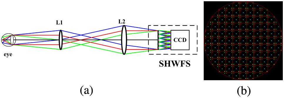
Fig. 1. (a) Layout of the SHWFS and (b) the image spots on the CCD in the SHWFS. L1 and L2 are used to accommodate to the pupil of the eye and the diameter of the SHWFS. The square indicates the subarea of the SHWFS. The five spots in every subarea are the images of five objects in the retina, respectively.
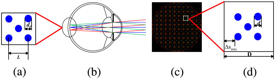
Fig. 2. (a) Multiple object arrangement pattern on the retina, L d e d D Δ S max
Fig. 3. Image spots on the CCD in the SHWFS with different dynamic ranges. Δ S max
Fig. 4. Centroid detection for wavefront reconstruction by the dynamic windowing method. (a) Part of the reference light spots array, (b) part of the aberration light spots array, and (c) light spots in the zoomed subarea.
Fig. 5. Wave-front for HEMA without tilt aberration. Unit of the color bar: μm.
Fig. 6. 1(a)–5(a) Reconstructed wavefront for the 5 objects and 1(b)–5(b) the residual wavefront between the test eye wavefront and the reconstructed wavefront. Unit of the color bar: μm.
Fig. 7. RMS of the residual aberration as a function of amplitudes of the test wavefront.
Fig. 8. Wide FOV improved by multiple object detection. (a) 7-object arrangement pattern on the retina, (b) image spots on the CCD, (c) 9-object arrangement pattern on the retina, and (d) image spots on the CCD. The blue circle is the isoplanatic patch area and white area is the area that could not be detected.
Fig. 9. 1(a)–7(a) Reconstructed wavefront for the 7 objects and 1(b)–7(b) the residual wave-front between the test eye wavefront and the reconstructed wavefront. Unit of the color bar: μm.
Fig. 10. 1(a)–9(a) Reconstructed wavefront for the 9 objects and 1(b)–9(b) the residual wavefront between the test eye wavefront and the reconstructed wavefront. Unit of the color bar: μm.
Fig. 11. Residual aberration between the reconstructed wavefront and the test eye aberration as HEMA for 5, 7, 9 objects.
Fig. 12. Layout of the two-object system.
Fig. 13. Image spots diagrams on the CCD. (a) spots from left object; (b) spots from right object; and (c) spots from two objects.
Fig. 14. Wavefront reconstruction of the left spot (a,c) and the right spot (b,d), as measured with singal object and double objects, respectively. Unit of the color bar: μm.
|
Table 1. Different Parameters for the Designed MOSHWFS
|
Table 2. Detailed Parameters of SHWFS

Set citation alerts for the article
Please enter your email address
© Copyright 2018-2021 | Chinese Laser Press. All Rights Reserved 沪ICP备15018463号-20