1State Key Laboratory of Applied Optics, Changchun Institute of Optics, Fine Mechanics and Physics, Chinese Academy of Sciences, Changchun 130033, China
2University of Chinese Academy of Sciences, Beijing, 100039, China
3Liquid Crystal Institute, Kent State University, Kent, OH 44242, USA
Lebao Yang, Lifa Hu, Dayu Li, Zhaoliang Cao, Quanquan Mu, Ji Ma, Li Xuan, "Multiple-object Shack–Hartmann wavefront sensor design for a wide field of view on the retina," Chin. Opt. Lett. 13, 120801 (2015)
Copy Citation Text
In order to detect the aberration from a wide field of view (FOV) on the retina with adaptive optics, we present a multiple-object Shack–Hartmann wavefront sensor (MOSHWFS) design. The simulated results indicate that the wavefront from our MOSHWFS can be reconstructed for multiple objects, and the measurement error can be less than with an MOSHWFS with an FOV of 6.7°, for maximum eye aberration. The experimental result with two objects indicates that the measurement error can be less than , with the root mean square of the reference wavefront as and , respectively.
Adaptive optics (AO) originating from astronomical observation techniques has been widely used in ophthalmology to obtain retinal images with high resolution[1–3]. However, the imaging field of view (FOV) on the retina is limited by the isoplanatic angle of the human eye, which leads to a small FOV ranging from 1.5° to 2.5° at a wavelength of 785 nm[4]. However, retina imaging clinic applications require a larger FOV for a large imaging area.
Several designs were reported to obtain a large FOV[5–7]. All of the reported Shack–Hartmann wavefront sensor (SHWFS) for large FOVs have several microlens arrays and/or CCDs, which makes the whole system expensive, complex, and have a large volume. To solve the problem, we present a design of a multiple-object SHWFS (MOSHWFS). It has a large FOV and simple structure like a traditional SHWFS with a large dynamic range and high precision. In addition, our method is cost effective and compact, even compared with scanning laser ophthalmology (SLO)[8,9].
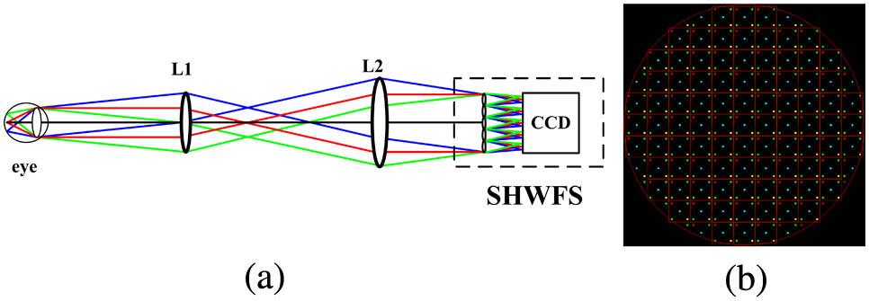
The presented MOSHWFS includes only one microlens array and a CCD, which is as simple as a single-object SHWFS. The schematic structure of the proposed MOSHWFS is shown in Fig. 1(a). Light from five objects on the retina with different fields goes through the optical relay lenses and reaches the CCD. Simulating the process with Zemax software, we get the light spots array shown in Fig. 1(b).
Sign up for Chinese Optics Letters TOC. Get the latest issue of Chinese Optics Letters delivered right to you!Sign up now
Figure 1.(a) Layout of the SHWFS and (b) the image spots on the CCD in the SHWFS. L1 and L2 are used to accommodate to the pupil of the eye and the diameter of the SHWFS. The square indicates the subarea of the SHWFS. The five spots in every subarea are the images of five objects in the retina, respectively.
The FOV of 6.7° is designed for the MOSHWFS, which is large enough for clinic applications. The specific parameters of five objects on the retina and their images are shown in Fig. 2. As the isoplanatic angle of the human eye is varied among objects in the range from 1.5° to 2.5°, we select the isoplanatic angle as 1.5° to accommodate most people’s eyes. However, the angle between the peripheral objects and the central object is 3.1°, which is larger than the isoplanatic angle. A simple eye model is shown in Fig. 2(b). The spots on the CCD are shown in Fig. 2(c) and the detail in one subaperture is shown in Fig. 2(d).
Figure 2.(a) Multiple object arrangement pattern on the retina, : the distance between two neighbor objects, : the diameter of the object on the retina; (b) model of the human eye; (c) image spots on the CCD of the MOSHWFS; (d) the detail in one subaperture, : the diameter of one image spot on the CCD, : the diameter of one microlens, : the maximum distance when the Shack–Hartmann image spot is displaced on the CCD within one microlens region.
Although we have a large FOV, it is most important to obtain a high precision and large dynamic range of the MOSHWFS for high-resolution imaging. So, it is necessary to avoid the cross talking of light spots by selecting reasonable number of CCD pixels in one subaperture and the magnification of the optic system.
The dynamic range () derived from Fig. 2(d) can be written as where is the focal length of the microlens. For convenience, we define as the size of several pixels; that is, , is the number of pixels, and is the pixel size. In theory, increasing the size of the microlens or decreasing the focal length can increase the dynamic range.
Considering the magnification of the system, the size of one image spot () on the CCD and the size of the microlens () can be calculated as where the aperture of a human eye pupil is 6 mm, and its focal length is 18 mm. is the microlens array number in the MOSHWFS ( in our case) and is the -number of the microlens.
For the corresponding results for the Liou–Brennan eye model with 3.1° for [7], we set four peripheral incoming object beams that are separated from the central object by a visual angle of 3.1° (880 μm), and the distance between the two peripheral objects is 1.24 mm. We choose the size of the object () as 50 μm as an ideal dot source for the simulation, and the wavelength of the detection light () as 808 nm. In addition, we select the -number of the microlens as 15, which is easy to fabricate in practice. Thus, the spot diameter is 52.35 μm.
In order to decrease the sampling error of the image spots on the CCD, we assume the ratio of the full width at half maximum (FWHM) of one spot and the pixel size of the CCD as 1.5 pixels; that is, one image spot occupies 3 pixels on the CCD, thus the CCD pixel size can be obtained as 17.45 μm (). Substituting these parameters into Eq. (2) the diameter can be calculated as
To optimize the dynamic range of the MOSHWFS, we calculate the parameters of the MOSHWFS for different ranging from 0 to 5 pixel in size. The results are listed in Table 1 and the simulated image spots on the CCD for each design are shown in Fig. 3. The red square in Fig. 3 is the size of one microlens in the SHWFS for multiple object detection. It shows that the dynamic range is increasing from 0 to 7.4 mrad from Figs. 3(a)–3(f). Therefore, we can modify the parameters to obtain a required dynamic range of the MOSHWFS, according to Eqs. (1) and (4). As the dynamic range increases, the distance between neighborhood light spots becomes longer. However, there is a balance between the dynamic range and the measurement precision. of 3 pixels corresponds to 4.9 mrad, which is good enough for retina aberration measurements.
ΔSmax(pixels)
D(μm)
f(mm)
Pixel Numbers on CCD
θmax(mrad)
0
615.9
9.24
389
0
1
650.7
9.76
411
1.8
2
685.5
10.28
433
3.4
3
720.3
10.80
455
4.9
4
755.1
11.33
476
6.2
5
789.9
11.85
798
7.4
Table 1. Different Parameters for the Designed MOSHWFS
Correspondently, the centroid detection algorithm in the proposed MOSHWFS is based on the dynamic windowing method[10]. The procedure to reconstruct a wavefront is as follows. First, measure the standard centroid positions of five objects without aberration [shown in Fig. 4(a)]. The red square is the size of one microlens and the five spots in the square are the image spots from five different objects. Second, calculate the centroid of light spots. The centroid position (red star) is shown in Fig. 4(b). The detail on the CCD in the region of one microlens is shown in Fig. 4(c).
Figure 4.Centroid detection for wavefront reconstruction by the dynamic windowing method. (a) Part of the reference light spots array, (b) part of the aberration light spots array, and (c) light spots in the zoomed subarea.
We select as 3 pixels in Table 1 as an example. As the size of the image spot is 3 pixels on the CCD and the is 3 pixels, the pixel number of the CCD is set as 461 pixels by 461 pixels since the design can be 455 pixels by 455 pixels according to Table 1, and 6 more pixels is necessary because of the dynamic window for the peripheral image spots. Due to increased CCD pixels for the simulation, the dimension of the 11 by 11 microlens array is 7.92 mm now, which is 1.32 times larger than the parameter in Table 1 (designed by 6 mm), so we select the focal lengths of L1 and L2 as 100 and 132 mm, respectively in Fig. 1, to accommodate the eye pupil and the diameter of the MOSHWFS.
To validate the efficiency of the MOSHWFS, a human eye maximum aberration (HEMA) is selected as the test wavefront. Its value is selected based on Thibos’ statistical results[11]. The peak-to-valley (PV) and root mean square (RMS) are and , respectively. The HEMA without tilt of the real eye is shown in Fig. 5. As the AO system does not need to correct the tilt aberration, we only simulate the situation without tilt aberration.
Figure 5.Wave-front for HEMA without tilt aberration. Unit of the color bar: μm.
The aberration in the pupil for five objects is all set with HEMA as the aberration is the maximum aberration for the human eye. The reconstructed wavefront is shown in Figs. 6[1(a)–5(a)], the residual aberration between the wavefront reconstructed and the standard wavefront are shown in Figs. 6[1(b)–5(b)]. The RMS of the residual aberration is , , , , and , respectively. The residual aberration is less than , which corresponds to 2 times the diffraction limit. Therefore, the MOSHWFS can measure the eye aberration for multiple objects in applications.
Figure 6.1(a)–5(a) Reconstructed wavefront for the 5 objects and 1(b)–5(b) the residual wavefront between the test eye wavefront and the reconstructed wavefront. Unit of the color bar: μm.
For more simulations, we measure the reconstructed wavefront when the test aberration is small. We preset the eye aberration as 0.2, 0.4, 0.6, 0.8, 1, 1.2, and 1.4 times HEMA, and then we measure the reconstructed wavefront for 5 objects (Fig. 7). When the aberration is larger than 1.2 times HEMA, the RMS of the residual aberration is less than . Thus, the MOSHWFS can measure the maximum aberration of about 1.2 times HEMA, meaning it can be used for open-loop AO when the eye aberration is less than 1.2 times HEMA. For the 1.4 times HEMA in the subaperture, parts of the light spots have deviated from their corresponding areas, so the error of the wavefront reconstruction is large.
Figure 7.RMS of the residual aberration as a function of amplitudes of the test wavefront.
The RMS of the residual aberration is smaller when the test aberration is smaller. When the eye aberration is smaller than 0.4 times HEMA, the RMS of the residual is less than . Thus, an MOSHWFS can be served to closed-loop AO when the eye aberration is less than 1.4 times HEMA.
Sign up for Chinese Optics Letters TOC. Get the latest issue of Chinese Optics Letters delivered right to you!Sign up now
In order to further increase the wavefront measurement area on the retina, we can use more objects. Figure 8 shows the simulations for 7 and 9 objects. The SHWFS with multiple pupil planes can only measure fixed numbers and fixed arrangement patterns of the objects, since it depends on the design of the collimating lens array and the size of the microlens, while the proposed SHWFS with a single pupil plane can simulate arbitrary multiple numbers and the arrangement pattern of multiple objects as long as the aberration from the multiple objects is limited to within the dynamic range of the SHWFS with proper designs.
Figure 8.Wide FOV improved by multiple object detection. (a) 7-object arrangement pattern on the retina, (b) image spots on the CCD, (c) 9-object arrangement pattern on the retina, and (d) image spots on the CCD. The blue circle is the isoplanatic patch area and white area is the area that could not be detected.
We simulate the measured aberration for 7 and 9 objects with our MOSHWFS. The test eye aberration is HEMA. The situation for 7 objects is shown in Fig. 9; the reconstructed wavefront for 7 objects is shown in Figs. 9[1(a)–7(a)] and the RMS of the residual aberration between the test aberration and the reconstructed wavefront is shown in Figs. 9[1(b)–7(b)], while the situation for 9 objects is shown in Fig. 10. For further illustration, we give the plot of the RMS of the residual aberration for 5, 7, and 9 objects (shown in Fig. 11). The maximum RMS of the 7 and 9 objects is less than 2 times the aberration of the diffraction limit, which is as same as the situation with 5 objects.
Figure 9.1(a)–7(a) Reconstructed wavefront for the 7 objects and 1(b)–7(b) the residual wave-front between the test eye wavefront and the reconstructed wavefront. Unit of the color bar: μm.
Figure 10.1(a)–9(a) Reconstructed wavefront for the 9 objects and 1(b)–9(b) the residual wavefront between the test eye wavefront and the reconstructed wavefront. Unit of the color bar: μm.
For simplification, a two-object system with an SHWFS for one object in hand is used to validate the presented method. Figure 12 shows the layout of the two-object system. The SHWFS is made by us and the detailed parameters of the SHWFS are listed in Table 2. The illuminating light source used here is a commercial laser diode (LD) with output wavelength 808 nm and diameter 0.2 mm. The angle of the two objects is about 0.2°. By changing the position of the point light source, we get the wavefront with aberration. The beams from the single mirror are shown in Figs. 13(a)–13(b) and the beam from the two mirrors is shown in Fig. 13(c).
We choose the reconstructed wavefront from the spot diagram [Figs. 13(a) and 13(b)] as the reference wavefront. Figures 14(a) and 14(b) show the wavefront from different fields with a single mirror; the RMS of the wavefront from the left and right object are and , respectively. Figures 14(c) and 14(d) are the reconstructed wavefront from the double mirrors. The RMS of the residual aberration from the single object and the double objects is (left object) and (right object). Although only the two-object wavefront reconstruction is used in the experiment, the proposed method is effective for multi-objects and the reconstructed wavefront error is less than .
Figure 14.Wavefront reconstruction of the left spot (a,c) and the right spot (b,d), as measured with singal object and double objects, respectively. Unit of the color bar: μm.
The design, simulation, and validation of an MOSHWFS with a single pupil plane are presented for a wide FOV on a retina. Simulations with 5 objects for the designed MOSHWFS with an FOV of 6.7° indicate that the RMS of the residual aberration in the wavefront reconstruction is less than 2 times the aberration of diffraction limit. In addition, when increasing the object number to 7 and 9, the RMS of the residual aberration is also less than , which corresponds to 2 times as much as the diffraction limit with the test aberration as HEMA. For more simulations with different test aberrations, the RMS of the residual aberration is smaller when the test aberration is smaller, and when the test aberration is less than 0.4 times HEMA and the RMS of the residual aberration is less than . Therefore, the designed MOSHWFS can measure aberrations with high accuracy for multiple-object detection for the human eye. In the next step, the fast wavefront reconstruction method for the MOSHWFS must be investigated and the liquid crystal AO based on the MOSHWFS will be used for a wide FOV image on retina AO. Furthermore, the design method of the MOSHWFS can be promising to be used in astronomical applications to obtain a large FOV and decrease the cost of the AO system.
Lebao Yang, Lifa Hu, Dayu Li, Zhaoliang Cao, Quanquan Mu, Ji Ma, Li Xuan, "Multiple-object Shack–Hartmann wavefront sensor design for a wide field of view on the retina," Chin. Opt. Lett. 13, 120801 (2015)