Beijing Key Lab for Precision Optoelectronic Measurement Instrument and Technology, School of Optoelectronics, Beijing Institute of Technology, Beijing 100081, China
A method based on the laser differential confocal principle is proposed for measurement of the uniformity of the inner and outer radius and shell thickness for an inertial confinement fusion (ICF) capsule. Firstly, this method uses the laser differential confocal measurement system (LDCS) driven by a precision air-bearing slide to scan and measure radially the outer radius, R, inner radius, r, and shell thickness, T, accurately. Secondly, a precision air-bearing rotation system is used to drive the capsule to rotate an angle, θ, in sequence, and the LDCS is used to measure R, r and T at the corresponding angle. Finally, the uniformity of the ICF capsule’s R, r and T can be calculated by the values of R, r and T measured at the position of each rotation angle. This method provides an approach for achieving high-precision, non-destructive, comprehensive, and rapid measurement of the uniformity of the inner and outer radius and shell thickness of an ICF capsule. Preliminary experiments indicate that measurement precision, using the proposed method for the uniformity of the outer radius, shell thickness and inner radius of the capsule, can reach 7.02 × 10?5, 5.87 × 10?4 and 6.52 × 10?5, respectively.
I. Introduction
The first achievement of fusion fuel gains exceeding unity by the US National Ignition Facility (NIF) is a significant milestone in the field of laser inertial confinement fusion (ICF) ignition. However, ignition is yet to be achieved. One of the main reasons is that the ICF capsule is squeezed asymmetrically during ignition.1,2 Geometrical parameters, such as uniformity of the inner and outer radius and shell thickness of the ICF capsule, are the key factors leading to the Rayleigh-Taylor instability.3 Therefore, high-precision measurement of the uniformity of the inner and outer radius and shell thickness of an ICF capsule is important for successful ignition.
At present, the nondestructive measurement methods for uniformity of the inner and outer radius and shell thickness of an ICF capsule mainly include the optical interference method4–7 and the X-ray method.8–13 The optical interference method calculates the inner and outer radius and shell thickness by recording the height of the inner and outer surface of the measured capsule, mounted on a flat piece of glass, and the off-centeredness of the interference fringes and the measurement accuracy is up to 0.05 μm. However, the method is very demanding on the surface roughness and transparency of the measured capsule.
To achieve measurement of the geometrical parameters of the opaque and translucent capsule, an X-ray method, with strong penetrating ability, has been proposed; this method mainly includes X-ray radiography8,9 and X-ray phase contrast imaging (XPCI).10,11 X-ray radiography is based on the principle that different materials absorb X-rays to different degrees. An unmagnified image of an ICF capsule, obtained by placing the capsule directly in contact with a photographic plate and then passing through X-rays, nearly parallel to the capsule, is processed digitally to achieve measurement of the ICF capsule’s geometrical parameters. However, this method has the disadvantages of a long exposure time and complex processing. Further, due to the limitation of principle, it is difficult to obtain high-contrast images for weak-absorption shells.
To improve measurement efficiency and obtain a high-contrast image of an ICF capsule, the XPCI method, based on the principle that the second-order differential of projected charge density is linearly related to the image intensity, is proposed to enhance image edge contrast, and the use of the charge coupled device (CCD) for capsule imaging simplifies data processing. Other measurement methods and systems based on XPCI have been developed, such as the X-ray tomography method,12 combining shell thickness reconstruction, spatial interpolation and edge recognition technology, and the precision radiography system,13 combining the X-ray method and a multi-channel photomultiplier. However, measurement accuracy of the above methods is limited by CCD pixel size.
Therefore, this paper proposes a laser differential confocal uniformity method for the measurement of inner and outer radius and shell thickness of ICF capsules. The proposed method utilizes the crossing zero point of the property curve of the laser differential confocal measurement system (LDCS) and the ray tracing algorithm14 to precisely calculate the outer radius, R, inner radius, r, and the shell thickness, T. Then, the capsule is rotated to other angle positions by the high-precision aerostatic rotary shaft, and at these angle positions, R, r and T are measured precisely again by LDCS. Finally, R, r and T, measured at all angle positions, are processed to achieve the high-precision measurement of the uniformity of the inner and outer radius and shell thickness of the ICF capsule. The proposed method provides an approach to the high-precision measurement of the uniformity of the ICF capsule’s inner and outer radius and shell thickness.
II. Measurement principle
A. Laser differential confocal geometrical parameters measurement principle for ICF capsule
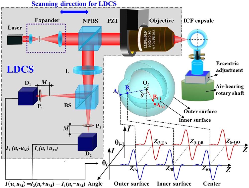
As shown in Fig. 1, the laser differential confocal uniformity of the inner and outer radius and shell thickness measurement principle for an ICF capsule is based on the property that the objective lens focus of the LDCS precisely corresponds to the zero point of the normalized, differential confocal intensity curve.15 Firstly, the LDCS is driven by a precision air-bearing slide to radially scan and focus point A on the outer surface, point B on the inner surface and the capsule center, point O, in sequence. In addition, the current position of LDCS is obtained in real time using a distance measurement instrument (DMI). The optical coordinates ZA, ZB and ZO precisely corresponding to points A, B and O, respectively, are calculated by the normalized differential confocal intensity curves IA, IB and IO, and then the outer radius, R, inner radius, r and shell thickness, T, of the ICF capsule can be calculated by a ray tracing algorithm. Secondly, it uses the high-precision aerostatic rotary shaft to rotate the capsule angle, θ, in sequence, and at the position of angle θ, it uses LDCS again to scan and measure R, r and T. Finally, all measured R, r and T are processed to obtain the uniformity of the inner and outer radius and shell thickness of the ICF capsule.
Figure 1.Laser differential confocal uniformity of the inner and outer radius and shell thickness measurement principle of an ICF capsule.
As shown in Fig. 1, an expander is used to expand the light beam emitted by the laser to form a parallel beam that can fill the pupil of the objective lens, and then the light is focused on the measured ICF capsule, after passing through a non-polarizing beam splitter (NPBS) and the objective lens. When point A on the outer surface, point B on the inner surface, and the capsule center point, O, are near the focus of objective, the light beam with the current position information is reflected to pass through the objective and NPBS again. After being converged by the lens, L, and split by a 5:5 beam splitter (BS), the two measurement beams are received by detectors D1 and D2 behind pinholes P1 and P2, respectively. The pinhole, P1, is placed behind the focal plane of lens, L, and the distance between P1 and the focal plane is M. Similarly, the pinhole, P2, is placed before the focal plane of lens, L, and the distance between P2 and the focal plane is also M. The differential confocal axial response curve I(u,uM) is obtained by the subtraction of the signals I1(u,−uM) and I2(u,+uM), received by D1 and D2, respectively,15where
Here, u and uM represent the axial optical normalized coordinate, and the axial normalized offset of the pinhole, respectively. Z is the axial optical coordinate, the laser wavelength is λ and the numerical aperture of the objective and lens, L, are respectively NA and NA1. The zero-crossing points of the axial response curves IA(u,uM), IB(u,uM) and IO(u,uM) accurately correspond to the optical coordinates of points A, B and O, and are denoted ZA, ZB and ZO, respectively.
Figure 1 shows that it uses the high-precision aerostatic rotary shaft to drive the capsule, to rotate in sequence, at an angle of θ = 2π/N (N is the sampling positions number on the equator section profile of the ICF capsule). As the capsule center, O, and the rotation system center, O′, cannot be perfectly aligned during rotation of the capsule, this will introduce focus errors to the measurements of ZA, ZB and ZO. As shown in Fig. 2, O0 is the initial position of the capsule center. Ci and Oi are the actual measured positions of the surface and center of the measured capsule at the ith sampling position (θi = 2πi/N), respectively. The initial angle between the capsule eccentricity, e, and the optical axis is φ, and the eccentricity, e, and angle, φ, can be calculated using the least-square circle (LSC) algorithm.16
Figure 2.Measurement errors introduced by the eccentricity, e, of the capsule.
According to geometric optics, the measurement errors ΔCAi, ΔCBi and ΔOi of points A, B and O at the ith sample position of the equator section profile of the capsule are, respectively,
The variable a satisfies respectively a = R and a = r when ΔCAi and ΔCBi are calculated. The optical coordinates after correction by Eqs. (3) and (4) of points A, B, and O at each sampling position of the equator section profile of the capsule are {} = {ZA1 + ΔCA1, …, ZAi + ΔCAi, …, ZAN + ΔCAN}, {} = {ZB1 + ΔCB1, …, ZBi + ΔCBi, …, ZBN + ΔCBN} and {} = {ZO1 + ΔO1, …, ZOi + ΔOi, …, ZON + ΔON}, respectively. Therefore, the outer radius, Ri, at the ith sampling position of the capsule equator section profile is Ri = − .
Due to the influence of the capsule shell refractive index, n, the measurement ray is deflected when it is passing through the capsule shell. According to the ray tracing algorithm, the aperture angle of the ray is β; the shell thickness, Ti, and the inner radius, ri, at the ith sampling position are calculated, respectively, as follows:where
Here, nair is the refractive index of air and nair = 1 (the influence of vibration and variations in humidity and temperature on nair can be neglected in the laboratory environment). The maximum, minimum and average of the outer radius are respectively denoted, Rmax, Rmin and Ravg, and the definitions of the maximum, minimum and average of the inner radius and shell thickness are similar to that of the outer radius. The outer radius uniformity, ξR, the shell thickness uniformity, ξT, and the inner radius uniformity, ξr are given respectively as17
B. Radial focusing property analysis of the inner and outer surface of the ICF capsule
Since there is no theoretical error in the ray tracing algorithm, the uniformity measurement accuracy of the inner and outer radius and the shell thickness of the ICF capsule mainly depend on the axial resolution, Δu, of LDCS. According to confocal optical microscopy theory, the axial resolution of LDCS is Δu = 0.89λ/NA2,18 and the axial resolution curve is shown in Fig. 3 for different NAs when λ = 633 nm.
Figure 3.Axial resolution curve, Δu, for different NAs of objective lens.
Figure 3 shows that the improvement of the axial resolution, Δu, of LDCS tends to be flat when NA is greater than 0.40. What’s more, in general, the larger the objective NA is, the shorter the working distance WD is. Therefore, considering the axial resolution and the working distance, the objective (OLMYPUS corporation) with NA = 0.80 and WD = 3.4 mm is selected in LDCS, and the axial resolution calculated is Δu = 0.88 μm, which meets the measurement requirements of the ICF capsule.
III. Experiments
A. Measurement system
Based on the measurement principle shown in Fig. 1, the sketch map of the laser differential confocal geometrical parameters measurement system for the ICF capsule is shown in Fig. 4.
The laser differential confocal geometrical parameters measurement system for the ICF capsule is mainly composed of the LDCS, high-precision aerostatic rotary shaft and air-bearing slider, DMI, eccentricity adjustment table and the computer measurement and control system. Each component contributes to scan and measure the positions of the ICF capsule’s inner and outer surface and center, the automatic eccentricity adjustment and rotation of ICF capsule, and the processing and evaluation of the measurement data.
Figure 5 shows the established laser differential confocal geometrical parameters measurement system for the ICF capsule. The system is fixed on an air floatation platform which can isolate vibration. In the system, the He-Ne laser, with wavelength λ = 633 nm and the OLMPLUS objective, with NA = 0.80 and WD = 3.4 mm, are used in LDCS. The focal length, fL, of convergent lens, L, and the diameter, DP, of the pinhole are respectively fL = 75 mm and DP = 20 μm. An XL-80 laser interferometer whose relative measurement precision can reach 1 × 10⁻⁶ and a corresponding environmental compensator used for real-time compensation of humidity and temperature are used as the DMI. The high-precision aerostatic rotary shaft with a radial gyration error better than 25 nm, made in our laboratory, is used in the measurement system. A NewFocus 8301NF is selected for the eccentricity adjustment actuator, with a travel range of 12.5 mm and a resolution better than 30 nm. The angle measuring device adopts an incremental encoder with a resolution of 0.91′, and a higher resolution can be achieved with an external subdivision circuit.
The measured ICF capsule with a shell refractive index of n = 1.4, which was screened early, was placed on the vacuum tube which was adjusted for eccentricity when the measurement system was assembled. In order to characterize the uniformity of the inner and outer radius and shell thickness of the ICF capsule, the sampling positions number needs to satisfy N ≥ 3.17 The capsule was driven to rotate at an angle of 90°, in sequence by the rotation shaft, i.e., 0°, 90°, 180°, 270°, which was monitored by the encoder in real time. Figure 6 shows the measured laser differential confocal curves of the inner and outer surfaces and center of the capsule. The optical coordinates of points A, B and O calculated by Eqs. (1)–(4) are respectively = −0.299 μm, = 32.994 μm, and = 440.331 μm, and then the outer radius of the capsule is R0 = − = 440.630 μm.
Figure 6.Differential confocal curves of the points A, B, and O.
According to Eqs. (5)–(8), the shell thickness, T0, and the inner radius, r0, can be calculated as T0 = 51.577 μm and r0 = R0 − T0 = 389.053 μm, respectively, and then the measured data at other angle positions are processed in the same way. The measurement results are shown in Table I.
0°
90°
180°
270°
R (μm)
439.981
441.175
440.630
443.456
T (μm)
51.200
51.664
51.577
51.630
r (μm)
388.781
389.511
389.053
391.826
Table 1. Measurement results of inner and outer radius and shell thickness of ICF capsule.
To further verify the stability and reliability of the measurement system, the outer radius, R, the shell thickness, T, and the inner radius, r, at the angle positions 0°, 90°, 180°, and 270°, were measured 5 times, resulting in the repeated measurement results shown in Figs. 7–9.
Figure 7.Repeated measurements of the outer radius, R.
Let the symbols σR, σT and σr represent, respectively, the repeated measurements of the standard deviation of the outer radius, R, shell thickness, T, and inner radius, r. The measurement results are shown in Table II.
0°
90°
180°
270°
σR (μm)
0.023
0.023
0.015
0.008
σT (μm)
0.019
0.021
0.025
0.014
σr (μm)
0.014
0.018
0.022
0.014
Table 2. Repeated measurements of the standard deviation of R, T and r.
The uniformities of the outer radius, R, and shell thickness, T, and inner radius, r, calculated by Eqs. (9)–(11) are shown in Figs. 10–12, respectively.
Figure 10.Repeated measurements of the outer radius uniformity.
According to the measurement data shown in Figs. 10–12, the repeated measurements standard deviation of the outer radius uniformity, σUR, the shell thickness uniformity, σUT and the inner radius uniformity, σUr are calculated as σUR = 7.02 × 10⁻⁵, σUT = 5.87 × 10⁻⁴ and σUr = 6.52 × 10⁻⁵, respectively.
IV. Conclusion
In this paper, we propose and develop a laser differential confocal uniformity method for measurement of the inner and outer radius and shell thickness with a high axial resolution of 0.88 μm for ICF capsules. Experimental results indicate that measurement precision can reach 7.02 × 10⁻⁵, 5.87 × 10⁻⁴ and 6.52 × 10⁻⁵ in the uniformity of the outer radius, shell thickness and inner radius measurements, respectively. The method not only realizes high-precision and non-destructive measurement of the capsule’s geometrical parameters, but also achieves only one loading and adjustment for the ICF capsule to achieve comprehensive and rapid measurement of the uniformity of the inner and outer radius and shell thickness of the ICF capsule.