
Hua-Ying Liu, Yao Zhang, Xiaoyi Liu, Luyi Sun, Pengfei Fan, Xiaohui Tian, Dong Pan, Mo Yuan, Zhijun Yin, Guilu Long, Shi-Ning Zhu, Zhenda Xie. High-speed free-space optical communication using standard fiber communication components without optical amplification[J]. Advanced Photonics Nexus, 2023, 2(6): 065001
- Advanced Photonics Nexus
- Vol. 2, Issue 6, 065001 (2023)
Abstract
Keywords
Free-space optical communication (FSO) has received increasing attention as an alternate to fiber communication for high-bandwidth wireless data transmission,1
Here we demonstrate FSO at 1 km distance with a data rate of 9.16 Gbps using a pair of commercial fiber-optical communication transceiver modules without optical amplification. Low average link loss of 13.7 dB, for the coupling into a single-mode fiber (SMF), is measured using our FSO devices, which is key for this demonstration of bidirectional optical communication. Such low link loss is enabled by the low-diffraction optical design, fully automatic four-stage closed-loop feedback control, and the motion stabilization system in our APT units. Without the need for optical amplifiers, a single FSO device only weighs 9.5 kg, within a size of and power consumption of ~10 W. Through integration of multisensors and the development of a corresponding algorithm, automatic, fast, and accurate acquisition and fine-tracking can be achieved within 10 min. Such an FSO device can be used in a pair for a single link or more pairs for multiple links in a plug-and-play manner to establish FSO channels in minutes, and thus fulfills the demand of field-deployable high-speed data transmission.
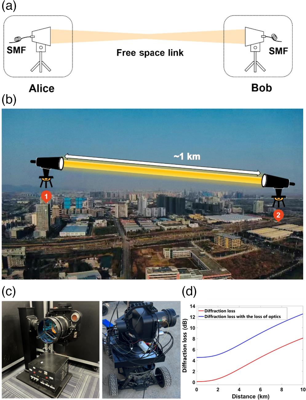
The scheme of our FSO communication is shown in Fig. 1(a), and a pair of FSO devices are used at two nodes with separation between 1 and 4 km. Alice is fixed at the top floor in our building, and Bob is loaded on a radio-controlled electric vehicle (RCEV) so that it can move around to change the FSO link distance for the experiments, as shown in Fig. 1(b). At both ends, our FSO devices feature identical optical aperture and mechanical design, as shown in Fig. 1(c). Each FSO device consists of an optical transceiver module, an APT unit and its control electronics, and both the transceiver module and the control electronics are sealed in a box for outdoor operation. Both FSO nodes are SMF-coupled, so that bidirectional optical communication can be achieved by the direct use of commercial optical transceiver modules. We choose the optical aperture of 90 mm in diameter and study the diffraction loss of the FSO link as a function of link distance. The result is shown in Fig. 1(d) and low diffraction can be calculated within a link distance of 10 km, considering the internal transmission of our optics.
Sign up for Advanced Photonics Nexus TOC. Get the latest issue of Advanced Photonics Nexus delivered right to you!Sign up now
![]()
Figure 1.(a) Scheme of our FSO. (b) Picture of the 1 km experimental field. (c) Picture of the FSO devices. Alice is fixed in the building and Bob is loaded on an RCEV. (d) Diffraction loss of our FSO system. Red, diffraction loss only; blue, diffraction loss with loss of optics.
Figure 2(a) shows the design of an FSO device. The blue part on the left shows the schematic of the optical part in an APT system, which is mounted on the three-axis gimbal stage for coarse tracking and active stabilization. The optical antenna is in a reflective Cassegrain design with 90 mm optical diameter and scale factor of 10:1, which is followed by the fine tracking optics. Three beacon laser (BL) diodes are used for the three-stage optical tracking, where BL0 (940 nm) and BL1 (638 nm for Alice, 660 nm for Bob)/BL2 (808 nm for Alice, 852 nm for Bob) are for the coarse tracking and first/second-stage fine tracking, respectively. Three complementary metal oxide semiconductor sensors (CMOS), CMOS0 and CMOS1/CMOS2, are used to generate the error signals for coarse tracking and first/second-stage fine tracking, respectively. The divergent angles of the three BLs are designed to be overlapped with each other so that APT process can be achieved stage by stage. While the beacon beam from BL0 and CMOS0 are placed off-axis from the signal beam, the beacon beam from BL1 and BL2 are concentric to the signal beam. The beacon beam from BL2 is from the same fiber as the FSO signal, and a wavelength division multiplexer (WDM) filter is used to separate this BL and communication signal. This fiber is connected to the optical transceiver module, with an optical circulator in between, for the separation of the up/down link optical signals.
![]()
Figure 2.(a) Design of FSO device. L, lens; IF, interference filter; DM, dichroic mirror; WDM, wavelength division multiplexer; TOSA, transmitter optical subassembly module; ROSA, receiver optical subassembly module; CMOS, complementary metal oxide semiconductor; BL, beacon laser; and FSM, fast steering mirror system (
With Bob moving on the RCEV, the FSO link can be established within 10 min using our APT systems once settled. The operation schematic of the APT system is shown in Fig. 2(b); its left part shows the mechanism of the active stabilization, initial acquisition, and coarse tracking processes using a three-axis gimbal in the APT system. The active stabilization is achieved using the rotational angular acceleration signal from an inertial measurement unit (IMU). This active stabilization isolates the APT system from the mechanical vibration during the FSO and ensures link stability. In the initial acquisition loop, the IMU is used to record the geomagnetic direction, the acceleration and angular acceleration, and a real-time kinematic (RTK) module is used to record the absolute position of the FSO device. By sharing these parameters between Alice and Bob, the relative angles between the two FSO devices, and thus pointing angles for both FSO devices, can be calculated by the designed algorithm. Then the initial acquisition is performed by feeding the pointing angles between Alice and Bob to the three-axis gimbal. After that, CMOS0 can detect the coarse tracking beam from BL0 in the opposite communication node for the error signal generation and takes over the control of the three-axis gimbal. Then the APT systems are ready for the fine optical tracking. CMOS1 detects the fine-tracking beam from BL1 and feeds back the error signal into FSM1, and a second-stage fine tracking is performed using CMOS2 and FSM2 in a similar mechanism to further increase the tracking accuracy on top of the first-stage fine-tracking loop, as shown in the right part of Fig. 2(b). The detailed parameters of the APT system are shown in Table 2.
| Link type | Working | Transmission | Optical | Optical | Weight | Size | Optical | Power | Tracking | Link loss | Reference |
| Satellite-ground | 400,000 km | 622 Mbps (downlink) | Yes | 100 mm (satellite) | 30 kg | — | Yes | — | Ref. | ||
| Airborne-ground | 50 km | 1.25 Gbps | Yes | 600 mm (ground) | — | — | Yes | — | 45 dB (20 km) 56 dB (40 km) | Ref. | |
| Airship-ship | 20 km | 1.5 Gbps | Yes | 120 mm | — | — | Yes | — | — | Ref. | |
| Helicopter-helicopter | 17.5 km | 1.5 Gbps | Yes | 120 mm | — | — | Yes | — | — | Ref. | |
| Fixed-wing aircraft-fixed-wing aircraft | 136 to 144 km | 2.5 Gbps | Yes | 120 mm | — | — | Yes | — | 58.3 dB | ||
| Satellite-ground | 450 km | 50/100 Mbps | Yes | 400 mm (ground) | 2.3 kg (satellite) | Yes | 22 W(satellite) | — | Ref. | ||
| UAV-ground | 7 km | — | — | 50 mm (UAV) | — | — | — | — | Ref. | ||
| Fixed end-RCEV | 1 km | 9.16 Gbps | No | 90 mm | 9.5 kg | No | 10 W | 13.7 dB | Our work |
Table 1. Sample of performance of recent FSO systems.
| Component | Value | |
| Coarse-tracking mechanism | Type | Three-axis motorized |
| Gimbal stage | ||
| Tracking range | Azimuth: | |
| Pitch: | ||
| (With roll fixed) | ||
| Coarse-tracking sensor | Type | CMOS |
| FOV | 0.04 rad * 0.04 rad | |
| Size and frame rate | 288 * 288 pixels and 1 kHz | |
| BL0 | Power | 1 W |
| Wavelength | 940 nm | |
| Divergence | 35 mrad | |
| Fine-tracking mechanism | Type | FSM |
| Range | ||
| Fine-tracking sensor | Type | CMOS |
| FOV | 13 mrad * 10 mrad | |
| Size and frame rate | 288 * 288 pixels and 1 kHz | |
| BL1 | Power | 5 mW |
| Wavelength | 638 nm and 660 nm | |
| Divergence | 6 mrad | |
| BL2 | Power | 5 mW |
| Wavelength | 808 nm and 852 nm | |
| Divergence | 6 mrad |
Table 2. Performance of the APT system.
We first measure the performance of the APT system in a 1 km FSO link. Figure 3(a) shows a tracking error with only coarse tracking open in a 120 s measurement, and the average error is , with standard deviation of 34.6 and for pitch and azimuth direction, respectively. Then we conduct a measurement of fine-tracking performance, with the result shown in Fig. 3(b). Only coarse tracking is open in the first 30 s, and the fine-tracking control is activated in the following 60 s. The result shows that once the first- and second-stage fine tracking is tuned on, the average tracking error is reduced rapidly from 24 to , with standard deviation of 2.9 and for pitch and azimuth direction, respectively. We measure the optical transmission loss using this FSO link, with results shown in Fig. 4(a). An average link loss is measured to be 29.3 dB with only first-stage fine tracking turned on (blue curve). The red curve shows the link loss with the second-stage fine tracking turned on and it reaches 13.7 dB, with standard deviation of 1.4 dB.
![]()
Figure 3.Performance of the APT system measured with 1 km separation. (a) Coarse tracking error. (b) Fine tracking error.
![]()
Figure 4.(a) Link loss for 1 km FSO. (b) Picture of the optical transceiver modules. (c) Communication bandwidth measurement for the module test and FSO. Red, direct connection test; blue, 1 km FSO test.
Then we use a pair of standard commercial fiber-optical transceiver modules for the FSO measurement. Both modules are rated at 10 Gbps, where the transmitter optical subassembly (TOSA) and receiver optical subassembly (ROSA) modules are both SMF-coupled in each module, as shown in Fig. 4(b). We first test the performance of these modules by direct fiber connections between Alice and Bob in their TOSA and ROSA ports, respectively. Using adjustable optical attenuators, identical losses can be applied for both links. The data rate is measured following the transmission control protocol via the software “open-source tool iperf3” (ESnet and Lawrence Berkeley National Laboratory).21 As shown in Fig. 4(c), the average data rate is measured at 9.27 Gbps during a 100 s test, and a maximum link loss exceeds 24.1 dB to reach such full bandwidth operation using these modules. Through the 1 km FSO link, the average data rate is measured to be 9.16 Gbps in a 100 s test, with a standard deviation of 0.24 Gbps. Hence, an almost identical data rate is achieved in the FSO link.
We further measure the APT performance in a 4 km FSO link, where the average link loss is measured to be 18 dB with standard deviation of 2.8 dB, as shown in Fig. 5. Compared with the 1 km link, the average link loss increases 4.3 dB. The maximum loss is 27.8 dB, which exceeds the tolerable maximum loss of the transceiver module. Hence, stable FSO link can hardly be achieved. Our experiment was conducted during the foggy winter in Nanjing with the air visibility generally around 4 to 5 km, which corresponds to absorption loss of at a 4 km distance.22 With better air quality or more sensitive optical transceiver module, we believe our FSO system can achieve optical communication at 4 km or longer distances.
![]()
Figure 5.Link loss for 4 km FSO.
In this work, we demonstrate 1 km FSO with a data rate of 9.16 Gbps using a pair of commercial fiber optical transceiver modules without optical amplification. This result shows that an FSO network may be achieved using standard fiber communication devices and network technology. Compact FSO devices are developed, with weight of only 9.5 kg. It is fast-field deployable and can be installed on an RECV for quick link change and FSO established within 10 min. We test our FSO link up to 4 km, and a maximum loss of 27.8 dB is measured. At such a loss level, FSO with the same high data rate can be expected at a longer range to a few kilometers with the use of EDFAs. In this experiment, we only test the FSO with both nodes fixed. Actually, our FSO system can also work when the RCEV is moving slowly and hence a mobile FSO link might be expected in a following study. Besides the classical FSO application, our compact APT systems can also be used to establish low-loss quantum links for transmission of quantum information.23,24
References
[1] W.-S. Tsai et al. A 20-m/40-Gb/s 1550-nm DFB LD-based FSO link. IEEE Photonics J., 7, 1-7(2015).
[2] H. Henniger, O. Wilfert. An introduction to free-space optical communications. Radioengineering, 19, 203-213(2010).
[4] B. Mukherjee, H. Kaushal et al. Free-space optical channel models. Free Space Optical Communication, 41-89(2017).
[22] L. Jingzhen. Handbook of Optics(2010).

Set citation alerts for the article
Please enter your email address
© Copyright 2018-2021 | Chinese Laser Press. All Rights Reserved 沪ICP备15018463号-20