• Infrared and Laser Engineering
  • Vol. 50, Issue 12, 20210046 (2021)
Lu Li1、2、3、4, Chenbo Xie1、3, Kunming Xing1、3, Bangxin Wang1、2、3, Ming Zhao1、3, and Liangliang Cheng1、2、3
Author Affiliations
  • 1Key Laboratory of Atmospheric Optics, Anhui Institute of Optics and Fine Mechanics, Hefei Institutes of Physical Science, Chinese Academy of Sciences, Hefei 230031, China
  • 2Science Island Branch of Graduate School, University of Science and Technology of China, Hefei 230026, China
  • 3Advanced Laser Technology Laboratory of Anhui Province, Hefei 230037, China
  • 4Faculty of Mechanical and Automotive Engineer, West Anhui University, Lu’an 237012, China
  • show less
    DOI: 10.3788/IRLA20210046 Cite this Article
    Lu Li, Chenbo Xie, Kunming Xing, Bangxin Wang, Ming Zhao, Liangliang Cheng. Optical-mechanical system design, installation and performance test of lidar with small-field and high-repetition frequency[J]. Infrared and Laser Engineering, 2021, 50(12): 20210046 Copy Citation Text show less
    Schematic diagram of lidar system structure with small-field of view and high-repetition frequency
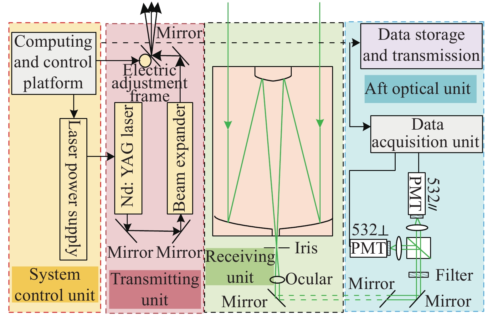
    Fig. 1. Schematic diagram of lidar system structure with small-field of view and high-repetition frequency
    Light path diagram of optical-mechanical system of the transmitting unit
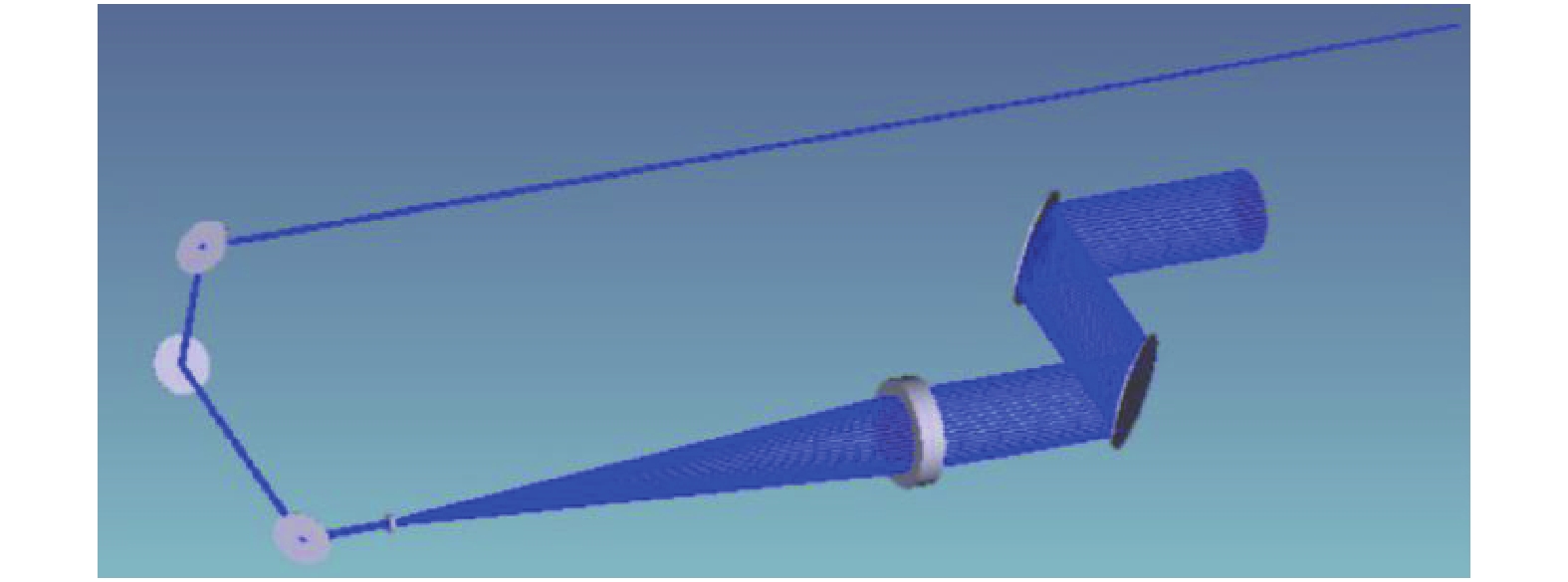
    Fig. 2. Light path diagram of optical-mechanical system of the transmitting unit
    Relation curve between incident angle and divergence angle after beam expansion
    Fig. 3. Relation curve between incident angle and divergence angle after beam expansion
    Optical-mechanical structure of transmitting unit
    Fig. 4. Optical-mechanical structure of transmitting unit
    Light path diagram of optical-mechanical system of the receiving and aft-optical unit
    Fig. 5. Light path diagram of optical-mechanical system of the receiving and aft-optical unit
    Light spot on the target surface of the detector under the field of view of 0.14 mrad (half angle)
    Fig. 6. Light spot on the target surface of the detector under the field of view of 0.14 mrad (half angle)
    Diffuse spots (a) and energy concentration (b) of telescope system under the field of view of 0.14 mrad (half angle)
    Fig. 7. Diffuse spots (a) and energy concentration (b) of telescope system under the field of view of 0.14 mrad (half angle)
    Eccentricity(a) and radius(b) of diffuse spot of the telescope system under different fields of view
    Fig. 8. Eccentricity(a) and radius(b) of diffuse spot of the telescope system under different fields of view
    Optical-mechanical structure of the receiving and aft optical unit
    Fig. 9. Optical-mechanical structure of the receiving and aft optical unit
    Lidar effective payload with small-field of view and high-repetition frequency
    Fig. 10. Lidar effective payload with small-field of view and high-repetition frequency
    Adjustment of optical-mechanical structure (a) and detection optical path of divergence angle (b) in transmitting unit
    Fig. 11. Adjustment of optical-mechanical structure (a) and detection optical path of divergence angle (b) in transmitting unit
    Detection (a) and results (b) of the wave aberration of telescope system
    Fig. 12. Detection (a) and results (b) of the wave aberration of telescope system
    Adjustment of optical-mechanical structure of receiving and aft optical units
    Fig. 13. Adjustment of optical-mechanical structure of receiving and aft optical units
    Original signal detected at 23:13 on October 11, 2020
    Fig. 14. Original signal detected at 23:13 on October 11, 2020
    Ratio of echo signal of S channel and P channel
    Fig. 15. Ratio of echo signal of S channel and P channel
    Profile of extinction coefficient (a) and depolarization ratio (b) detected at 12:00 on November detected at 00:24 on October 12, 2020
    Fig. 16. Profile of extinction coefficient (a) and depolarization ratio (b) detected at 12:00 on November detected at 00:24 on October 12, 2020
    Profile of extinction coefficient (a) and depolarization ratio (b) detected at 12:00 on November 04, 2020
    Fig. 17. Profile of extinction coefficient (a) and depolarization ratio (b) detected at 12:00 on November 04, 2020
    ItemParameters
    LaserWavelength/nm532.18
    Repetition rate/kHz3
    Output divergence2 (full)
    Output beam energy1
    Beam expansion20X
    TelescopeDiameter/mm125
    Field of view0.28(full)
    Focal length/mm1430
    Diffuse spots/mm<0.045
    Wavefront difference<1/4λλ=632.8 nm)
    Focal length of ocular/mm50
    Reflector(532 nm)R:99%
    Filter bandwidth/nm0.3
    Extinction ratio of polarizing prism3000:1
    DetectorPMT
    Capture cardPhoton
    Table 1. System parameters of lidar with small-field and high-repetition frequency
    Radius of curvature/mmDistance to the next side/mmRadius/mmQuadric coefficient
    −516−200680
    −141.536321.82176.288
    Table 2. Optical parameters of telescope of lidar with miniaturization and high-repetition frequency
    Lu Li, Chenbo Xie, Kunming Xing, Bangxin Wang, Ming Zhao, Liangliang Cheng. Optical-mechanical system design, installation and performance test of lidar with small-field and high-repetition frequency[J]. Infrared and Laser Engineering, 2021, 50(12): 20210046
    Download Citation