Qi-Xiang ZHAO, Meng-Shi MA, Xiang LI, You LV, Tian-Zhong ZHANG, Lin PENG, E-Feng WANG, Jin-Jun FENG. The multi-modes, multi-harmonics behavior of a THz large-orbit gyrotron[J]. Journal of Infrared and Millimeter Waves, 2022, 41(2): 457
Copy Citation Text
In this paper, a LOG capable of operating from the 4th to the 9th harmonic is designed and investigated. With the assistance of the 3-D particle-in-cell simulation, the key features of the designed LOG, beam-wave interaction dynamics and high-harmonic operation regimes are studied. It is shown that by tuning the external magnetic field intensity, successive excitation of the oscillation at a number of neighboring harmonics can be achieved, corresponding to radiation frequencies between 240 GHz to 460 GHz with the maximum radiation power of 19 kW. Then, a detailed study on the competitions among the 7th, 8th and 9th harmonics are conducted, providing an insight into the multi-modes, multi-harmonics behavior of the high-harmonic LOG. Following that, the methods to stabilize the beam-wave interaction and enable single mode operation at high harmonics are discussed. Additionally, the characterization of the ohmic loss power at different operation harmonics is conducted.
The high harmonic operation of a gyrotron is attractive for the great potential of reducing the required external magnetic field strength[1-8],which however may induce considerable mode competition problem. One of the most promising methods of enabling the beam-wave interaction at high harmonic while suppressing the mode competition is to use the axis-encircling electron beams,being known as the large-orbit gyrotron(LOG). In the past decades,the LOGs have been studied extensively in the millimeter wave band [9-13],including linear theory and nonlinear theory,high harmonic simulation and experiment. In recent years,due to the increasing needs of THz gyrotrons with realistic external magnetic field intensity,even higher harmonic oscillation of the LOG has also been studied numerically,to explore the possibility of further reduction of the external magnetic field strength [14-15]. It is shown that the excitation of even higher harmonic operation is achievable with the existing electron beam sources. However,due to the high density of mode spectrum and low beam-wave coupling coefficient at high harmonics,the problems of mode competition and unstable oscillation are discovered [16]. To solve these challenges,an insight into the multi-modes,multi-harmonics behavior should be gained. Also,for high harmonics operation,the ohmic loss issue plays an essential role,a study of which will be beneficial for the development of the high power THz LOGs.
In this paper,a high harmonic LOG in the THz band has been designed and studied. The designed cavity supports the beam-wave interaction from the 4th to the 9th harmonic,with the corresponding output frequency from 240 GHz to 460 GHz. The cold cavity analysis is employed to characterize a number of modes which are suitable for operating at the designed harmonics. Following that,the 3-D particle-in-cell(PIC)simulation is performed,the results of which show good agreements with the cold cavity analysis. Upon verifying the model,the multi-modes,multi-harmonics behaviors among the 7th,8th and the 9th harmonic are investigated. The competition among neighboring harmonics,the output power variation and the radiation spectrum evolvement are analyzed in detail. Then the dynamic range of the external magnetic field and the electron beam current for the stable single harmonic,single mode operation is deduced. Finally,the ohmic loss variation with time and the operation harmonics are characterized.
The remaining part of this paper is organized as follows:Part Two presents the beam-wave interaction cavity design and performs an overall analysis of the candidate modes for the high harmonic operation by the cold cavity theory. Part Three shows the numerical simulation result of the 3-D PIC simulations and its comparison with the cold cavity analysis results,to give an overview of the operation characteristics and verify the gyrotron design. Part Four investigates in detail the multi-modes,multi-harmonics behavior of the designed gyrotron,after which the stable single mode operation regime for the high harmonic operation is identified. The impact of ohmic loss issue is also analyzed. Part Five concludes this paper and suggests the future work.
1 Gyrotron design and cold cavity analysis
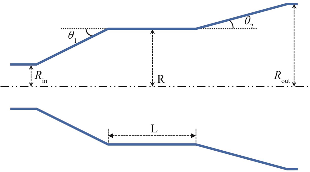
It has been shown in the previous studies that,to enable the beam-wave interaction at high harmonics,an axis-encircling electron beam with high voltage should be used. Thus the literature reported large orbit electron beam with a beam voltage of 250 kV,beam current of up to 10 A,velocity ratio of 2.0 is selected in this study[3]. Other electron beam sources with high current may also be used. The beam-wave interaction cavity is shown in Fig. 1,which is mainly composed of three sections,the input cone,the cylindrical waveguide for beam-wave interaction and the output cone. To achieve good separation of the operation magnetic field ranges for the neighboring modes and lower the starting oscillation currents of the designed modes,the length of the center cavity is designed as 10 mm,which equals to 14 wavelengths at 420 GHz. Other designed parameters are shown in Table. 1.
Parameters
Value
the length of the middle cylindrical waveguide
10 mm
the radius of the middle cylindrical waveguide
1.1 mm
the input radius of the input cone
0.8 mm
the output radius of the input cone
1.3 mm
The angle between the input cone and middle cylindrical waveguide
6°
The angle between the output cone and middle cylindrical waveguide
4°
Table 1. The geometric parameters of the LOG cavity
Since the traditional small-orbit gyrotron has been demonstrated from the fundamental to the third harmonic,this study will focus on the characterization of even higher harmonic operations. According to the previous analysis of the LOG [14],the harmonic operation can be effectively supported by the modes,given that equals to. Thus the modes()are selected to support the operation from the 4th to the 9th harmonic operation,respectively. These modes describe different quality factors and oscillation frequencies in the designed cavity. The quality factor of a mode in the designed cavity can be expressed as
,
where and are the diffraction quality factor and ohmic loss quality factor,respectively. can be estimated by
,
in which is the skin depth and . is the oscillation frequency of mode inside the cavity. and are the absolute permeability and the conductivity of the oxygen-free copper that is used as the cavity material.
The diffraction quality factors and the oscillation frequencies of the modes can be calculated by the linear theory with proper boundary conditions at the input and output ends of the cavity. The calculated values of quality factors and oscillation frequencies for the six modes are shown in Fig. 2. It can be seen that for modes operation,the oscillation frequency rises as the value of increases,while the value of the ohmic loss quality factor drops slightly as increases. This can be interpreted by observing the radial distributions of the modes’ electric field as shown in Fig. 3. It is shown that as increases,the field maxima moves towards the cavity wall. This will cause more ohmic loss,and thus describe smaller values of. While decreases slowly as increases,the value of increases dramatically with the azimuthal index rises. This can also be explained by observing the axial distribution of the modes electric field. As increases,the field is located more and more closely to the cavity wall,which will be more and more sensitive to the reflection at the output end of the cavity. According to the approximate expression in Ref.[17]for with multiple-reflection ,where is the effective length of the interaction section, is the axial index of mode,is the free-space wavelength of the resonant mode,and is the reflection coefficient for a wave at the resonant frequency,it is obvious that the mode with higher reflection at the output end of the cavity would have higher diffractive quality factor. Thus the mode with higher azimuthal index describes higher values of. Moreover,the difference on total quality factor between neighboring modes decreases as rises,thus the starting currents of high order mode would be very close,which implies intense mode competition during high-harmonic operation of LOGs. However,it should be noted that the competition mode spectrum density in the high-harmonic LOGs is much lower than the small-orbit counterparts,due to the strong mode selectivity of the axis-encircling electron beams.
Figure 2.The variation of the total quality factor,diffraction quality factor,ohmic loss quality factor and the oscillation frequencies of the designed modes with the azimuthal index()
Figure 3.Radial distribution of the azimuthal electric field for modes(=4∼9). and denotes the azimuthal and radial coordinate,respectively. is the first derivative of order Bessel function. is the waveguide radius
A nonlinear self-consistent code based on the nonlinear theory presented in Ref.[18]is developed in-house to simulate the beam-wave interaction in the designed LOG. The electron beam current can be chosen as low as 3 A,which is sufficient for the start-up of all the modes based on the analysis of the starting oscillation current of the five modes as shown in Fig. 4. When the beam voltage is set as 250 kV and the pitch factor is 2.0. The output power levels and resonant frequencies of, and with different magnetic fields are plotted in Fig. 5,in which the cavity wall is set as ideal conductor. The maximum powers of, and can reach 48.15 kW,40.17 kW and 75.48 kW,respectively,and the operating frequencies are 464.8 GHz,418.7 GHz and 372.3 GHz. Evidently,there is an overlap operation region where the operating mode transits to,also when transits to. This can be analytically explained by the uncoupled dispersion relationship between the electron beam and the waveguide mode as plotted in Fig. 6. When the magnetic field is 2.71 T,the dispersion curves of and (,where is the cutoff frequency of the mode in waveguide)can intersect with the synchronism curve(,wheredenotes the axial velocity and is the electron cyclotron frequency)at the positive propagation constant,meaning that and can interact with electron beam at this condition. Similarly, and can interact with electron beam when the magnetic field is 2.76T.
Figure 4.The starting current variation with external magnetic field,where the beam voltage is 250 kV,the pitch factor is 2.0
The output power and frequency with the different beam current are displayed in Fig. 7,in which the magnetic fields for,, are 2.77T,2.74T and 2.71T,respectively. It can be seen that there exists some obvious frequency jump points at certain beam currents(the current is 3.5 A for,4.0 A forand 4.5A for),that is because the LOG is operating at high order axial modes(HOAMs).
Figure 7.The nonlinear output power and output frequency variations with the beam current when the magnetic fields for,, are 2.77 T,2.74 T and 2.71 T,respectively
The above parameters are then applied in the modeling with the 3-D PIC simulation software,CST Studio Suite 2019,under the typical computer hardware with the CPU of Intel Core i7-8700(12 cores)and GPU with NVidia Tesla K40c. One of the typical numerical simulation results at the ninth harmonic with the mode are shown to validate the numerical model. When the external magnetic field strength is chosen as 2.71 T and the beam current is 3 A,and the wall conductivity is,the single mode operation of is observed from Fig. 8. The transverse field distribution shows that the operation mode is mode with 18 azimuthal peaks and only one radial peak. Correspondingly,the axial electric field distribution on the cavity wall is also recorded on a longitudinal cut plane. Only one peak is observed in the axial direction,meaning that the axial index of the operation mode is 1. Based on the combination of the observations in Fig. 8,a single mode operation of at the ninth harmonic is verified. The variations of the mode amplitude of with time is shown in Fig. 9. The beam-wave interaction stabilized at about 60 ns with the output power of 4.77 kW. The spectrum of the output signal shows that the operation frequency of the mode is 463.62 GHz,which confirms that the mode is oscillating at the 9th harmonic.
Figure 8.The electric field distribution of the mode obtained by CST simulation (a) the axial electric field distribution, (b) the transverse electric field distribution
The values of and can also be derived from the above PIC simulations results. The cold cavity results and the PIC simulated ones are compared in Table. 2. It is found that the operation frequency and diffractive quality factor in the PIC simulation are both lower than the cold cavity results because of the existence of electron beam. Good agreement on Ohmic quality factor has been achieved between the two,which also validates the above model.
Parameters
Cold cavity simulation
Hot cavity simulation
Oscillation Frequency/GHz
464.82
463.62
Ohmic quality factor
3 390.8
3 802.3
Diffractive quality factor
10 328
4 484
Total quality factor
2 552.7
2 057.6
Table 2. The comparison between the cold cavity analysis and hot cavity simulations
After verifying the numerical model,the multi-modes,multi-harmonics behavior of the designed LOG can be characterized. To maintain reasonable computation time,this study is focused on the 7th,8th and 9th harmonic operation. The study of the 4th to the 6th harmonic operation is less challenging and can be achieved in the same fashion. Mode spectrum regarding the external magnetic field is investigated.
3.1 Mode spectrum regarding the external magnetic field
When the beam voltage is 250 kV and beam current is 3.0 A,the output power and frequency variations with the external field is plotted in Fig. 10. It can be seen that only is operating at 2.69 ~2.71 T with the maximum power of 4.77 kW and frequency of 463.25 GHz,only is operating at 2.72 ~2.75 T with the maximum power of 7.75 kW and frequency of 417.65 GHz,and only is operating at 2.76~2.79 T with the maximum power of 7.90 kW and frequency of 371.6 GHz. By comparison with the results in Fig. 5,it is found that cannot be oscillated at 2.71 T and 2.76 T. This is because the wall loss is considered in the PIC simulation,the value decreases and the mode starting oscillation current increases [18]. Due to the cavity ohmic loss,not only the output power is reduced,but also the optimal magnetic field at the highest efficiency is increased. The output power degradation factor can be approximated as()[19]. The ohmic loss also leads to the shrink of the operating magnetic field region. It can be seen from Fig. 10 that the operational magnetic field regions for and are 0.03 T and 0.03 T,respectively,which are lower than the widths predicted in the aforementioned non-linear analysis(0.07 T and 0.06 T,respectively). This phenomenon is also found in Ref.[20].
Figure 10.The output power and output frequency variations with the external magnetic field when the beam voltage is 250 kV and beam current is 3.0 A
The above analysis and simulation results can be further verified by the agreement with the well-established fundamentals of cyclotron resonance maser theory,as shown in Fig. 11. Before the oscillation starts,the electron beam is evenly distributed in the azimuthal direction,as the case shown in Fig. 11(a). When the beam-wave interaction reaches the steady state at harmonic,where the wave frequency is about times the gyrating frequency of the electrons as governed by,there will be decelerating phase centers corresponding to electrons’ bunching centers in the azimuthal direction,as shown in Figs. 11(b-d). Such an observation is also described in the theory of conventional small-orbit gyrotrons with harmonic operations[19]. It can also be interpreted that during the steady state of oscillation,most of the electrons are releasing energy to the field,as the gyrating radii have decreased from the comparison with the unperturbed state. Moreover,it is found that the bunching centers when B is 2.77 T are more obvious than these when B is 2.71 T and 2.73T,meaning that the beam wave interaction intensity at 2.77 T is strongest. It is clear from Fig. 10 that the output power at 2.77 T is higher compared with those at 2.71 T and 2.73T.
Figure 11.The transverse view of the electron beams when operating at different harmonics(a)the unperturbed large-orbit electron beams,(b)the azimuthal bunching at the 9th harmonic(when B=2.71 T),(c)the azimuthal bunching at the 8th harmonic(when B=2.73 T),(d)the azimuthal bunching at the 7th harmonic(when B=2.77T)
Figure 12 shows the mode competition between and when the external magnetic field is 2.77 T. It can be seen that is firstly excited in the design cavity with the maximum power of 0.52 kW and the frequency of 417.97 GHz. After 55 ns, starts to be excited and finally reaches the steady state. Due to the excitation of,is totally suppressed. The PIC simulation results are consistent with the cold-cavity analysis results. The starting currents of and at 2.77 T are both below 3 A,thus these two modes might be excited. However,the starting current of is lower than,means that this operating point is located at the soft-excitation region of. Therefore,the excitation of would suppress the interaction between and electron beam.
Figure 12.The output amplitude variation with time when B=2.77 T and I=3 A. The inset is the spectrum of the output signal.
Figure 13 displays the output power and frequency variations with wall conductivity when B=2.72 T and I=3A. It is shown that the output power increases with the rise of wall conductivity,but the operating frequency is almost the same. Based on Eq. 2,it is known that the increase of wall conductivity leads to the drop of ohmic loss,thus the diffractive power would increase. Moreover,it is also found that when the wall conductivity is below,cannot be excited in the cavity because the starting current increases higher than 3A.
Figure 13.The output power and frequency variation with wall conductivity when B=2.72 T and I=3A.
Under different magnetic field,the output power and frequency variations with the beam current are shown in Fig. 14. It can be seen that the output powers at 2.71 T and 2.77 T increase with the rise of beam current and the output frequencies are almost unchanged. The operating modes are confirmed as and,respectively. By comparison with Fig. 7,the minimum operating current of is enhanced from 1.5 A to 3.0 A due to the wall conductivity,and that of is increased from 1.0 A to 2.5 A. Meanwhile,the output powers of and in PIC simulation are both lower than that in nonlinear analysis. At the magnetic field of 2.72 T,it can be seen that is suppressed due to the oscillation of with the powers of 2.05 kW and 2.86 kW when the beam current is increased to 3.5 A and 4.0 A. However,is again excited at the power of 17.05 kW as shown in Fig. 15 when the beam current is 4.5 A.
Figure 14.The output power and output frequency variation with the beam current when the external magnetic field is 2.71 T,2.72 T,and 2.77 T,respectively
In this paper,a high harmonic gyrotron in the THz range has been designed and studied. Based on nonlinear analysis,the designed cavity can operate at, and by tuning the external magnetic field to enable the beam wave interaction at 7th,8th and 9th. The maximum powers of, and can reach 48.15 kW,40.17 kW and 75.48 kW when the beam current is 3.0A and voltage is 250 kV. With the assistance of the 3-D particle-in-cell simulation,the key features of the designed LOG,such as the beam-wave interaction dynamics,high-harmonic operation regimes,mode competition and ohmic loss are studied. Based on the simulation results,it is shown that the designed LOG can stably generate high power terahertz radiation at high-harmonic operation. It is also verified that high-harmonic LOG is a promising approach to reduce considerably the required external magnetic field by THz gyrotrons.
Qi-Xiang ZHAO, Meng-Shi MA, Xiang LI, You LV, Tian-Zhong ZHANG, Lin PENG, E-Feng WANG, Jin-Jun FENG. The multi-modes, multi-harmonics behavior of a THz large-orbit gyrotron[J]. Journal of Infrared and Millimeter Waves, 2022, 41(2): 457