• Chinese Journal of Lasers
  • Vol. 48, Issue 21, 2105001 (2021)
Xichun Zhang1, Jinguang Lü2, Chong Zhang3, Wensheng Fu1, Xin Zhao1, Weiyan Li1, and He Zhang1、*
Author Affiliations
  • 1State Key Laboratory of High Power Semiconductor Lasers, Changchun University of Science and Technology, Changchun, Jilin 130022, China
  • 2State Key Laboratory of Applied Optics, Changchun Institute of Optics, Fine Mechanics and Physics, Chinese Academy of Sciences, Changchun, Jilin 130033, China
  • 3The First Military Representative Office of the Army in Changchun, Changchun, Jilin 130033, China
  • show less
    DOI: 10.3788/CJL202148.2105001 Cite this Article Set citation alerts
    Xichun Zhang, Jinguang Lü, Chong Zhang, Wensheng Fu, Xin Zhao, Weiyan Li, He Zhang. Multiple Bottle Beams Based on Metasurface Light Field Control[J]. Chinese Journal of Lasers, 2021, 48(21): 2105001 Copy Citation Text show less
    Schematic diagram of optical system
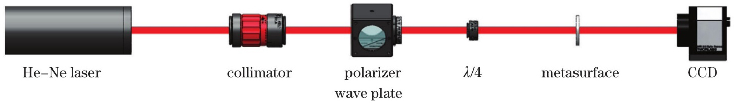
    Fig. 1. Schematic diagram of optical system
    Schematic diagram of the nano-pillar unit and the relationship between its rotation angle and related parameters. (a) Schematic diagram of a single nano-pillar unit; (b) relationship between the rotation angle of the nano-pillar unit and the transmittance(triangular line),polarization conversion efficiency(circular line), PB phase(square line)
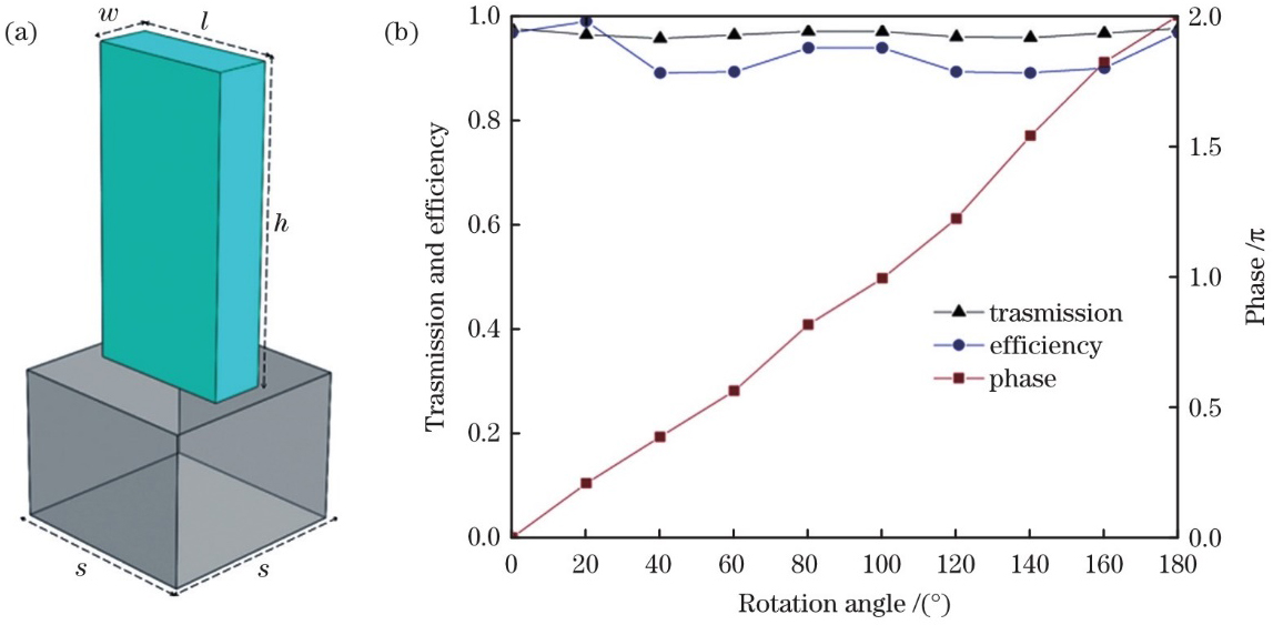
    Fig. 2. Schematic diagram of the nano-pillar unit and the relationship between its rotation angle and related parameters. (a) Schematic diagram of a single nano-pillar unit; (b) relationship between the rotation angle of the nano-pillar unit and the transmittance(triangular line),polarization conversion efficiency(circular line), PB phase(square line)
    Schematic diagram of hyperbolic phase metasurface and light field distributions. (a) Three-dimensional schematic diagram of the hyperbolic phase distribution metasurface; (b) light field distribution of the metasurface along the beam propagation direction; (c) focal plane light field distribution of the metasurface along the beam propagation direction
    Fig. 3. Schematic diagram of hyperbolic phase metasurface and light field distributions. (a) Three-dimensional schematic diagram of the hyperbolic phase distribution metasurface; (b) light field distribution of the metasurface along the beam propagation direction; (c) focal plane light field distribution of the metasurface along the beam propagation direction
    Schematic diagram, light field distribution and phase curves of the metasurface with an annular obstacle added. (a) A three-dimensional schematic diagram of the metasurface with the annular obstacle added; (b) optical field distribution of the outer ring part of the metasurface (radius R3) along the beam propagation direction; (c) focal plane light field distribution of Fig.4 (b); (d) hyperbolic phase and conical phase comparison chart, where the blue dotted line is the hyperbolic phase distribution, the solid line is the conical phase distribution, and the inset is an enlarged view of the two phase distributions in a radius of 10~12 μm
    Fig. 4. Schematic diagram, light field distribution and phase curves of the metasurface with an annular obstacle added. (a) A three-dimensional schematic diagram of the metasurface with the annular obstacle added; (b) optical field distribution of the outer ring part of the metasurface (radius R3) along the beam propagation direction; (c) focal plane light field distribution of Fig.4 (b); (d) hyperbolic phase and conical phase comparison chart, where the blue dotted line is the hyperbolic phase distribution, the solid line is the conical phase distribution, and the inset is an enlarged view of the two phase distributions in a radius of 10~12 μm
    Schematic diagram, light field distribution and linear distribution of the metasurface with ring-shaped obstacle added. (a) A two-dimensional schematic diagram of the metasurface with the annular obstacle added; (b) optical field distribution of the spherical wave generated by the inner ring; (c) optical field distribution of the Bessel light generated by the outer ring; (d) optical field distribution of the array local hollow beam; (e) linear distribution of spherical wave in Fig.5(b); (f) linear distribution of Bessel light in Fig.5(c); (g) linear distribution of the multiple hollow beam in Fig.5(d)
    Fig. 5. Schematic diagram, light field distribution and linear distribution of the metasurface with ring-shaped obstacle added. (a) A two-dimensional schematic diagram of the metasurface with the annular obstacle added; (b) optical field distribution of the spherical wave generated by the inner ring; (c) optical field distribution of the Bessel light generated by the outer ring; (d) optical field distribution of the array local hollow beam; (e) linear distribution of spherical wave in Fig.5(b); (f) linear distribution of Bessel light in Fig.5(c); (g) linear distribution of the multiple hollow beam in Fig.5(d)
    Multiple bottle beam light field diagram and linear diagram. (a) Optical field distribution in the beam propagation direction of the multiple bottle beam; (b) (c) optical field distribution at 9.45 μm and 11.54 μm; (d) linear distribution of Fig.6(a), in which the longitudinal FWHM of the two hollow beams are 0.9 μm and 1.2 μm, respectively; (e)(f) linear distribution of Fig.6(b) and Fig.6(c), and their transverse FWHM are 0.47 μm and 0.61 μm, respectively
    Fig. 6. Multiple bottle beam light field diagram and linear diagram. (a) Optical field distribution in the beam propagation direction of the multiple bottle beam; (b) (c) optical field distribution at 9.45 μm and 11.54 μm; (d) linear distribution of Fig.6(a), in which the longitudinal FWHM of the two hollow beams are 0.9 μm and 1.2 μm, respectively; (e)(f) linear distribution of Fig.6(b) and Fig.6(c), and their transverse FWHM are 0.47 μm and 0.61 μm, respectively
    Influence of different relative aperture values on the light field of local hollow beam. (a) A two-dimensional optical field distribution diagram of an array local hollow beam with different RA along the beam propagation direction; (b) linear fit of different RA and transverse FWHM; (c)linear fitting of different RA and radial FWHM
    Fig. 7. Influence of different relative aperture values on the light field of local hollow beam. (a) A two-dimensional optical field distribution diagram of an array local hollow beam with different RA along the beam propagation direction; (b) linear fit of different RA and transverse FWHM; (c)linear fitting of different RA and radial FWHM
    Two-dimensional light field distribution diagrams of a metasurface with different apertures of an annular obstacle along the beam propagation direction. (a) R2=5 μm; (b) R2=6 μm; (c) R2=7 μm
    Fig. 8. Two-dimensional light field distribution diagrams of a metasurface with different apertures of an annular obstacle along the beam propagation direction. (a) R2=5 μm; (b) R2=6 μm; (c) R2=7 μm
    Xichun Zhang, Jinguang Lü, Chong Zhang, Wensheng Fu, Xin Zhao, Weiyan Li, He Zhang. Multiple Bottle Beams Based on Metasurface Light Field Control[J]. Chinese Journal of Lasers, 2021, 48(21): 2105001
    Download Citation