
Guanghao Rui, Ying Li, Sichao Zhou, Yusong Wang, Bing Gu, Yiping Cui, Qiwen Zhan. Optically induced rotation of Rayleigh particles by arbitrary photonic spin[J]. Photonics Research, 2019, 7(1): 69
- Photonics Research
- Vol. 7, Issue 1, 69 (2019)
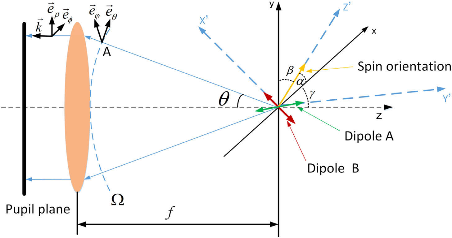
Fig. 1. Calculation of the pupil field to obtain a focused beam with arbitrary photonic spin orientation through coherent superposition of the radiation patterns from electric dipoles.
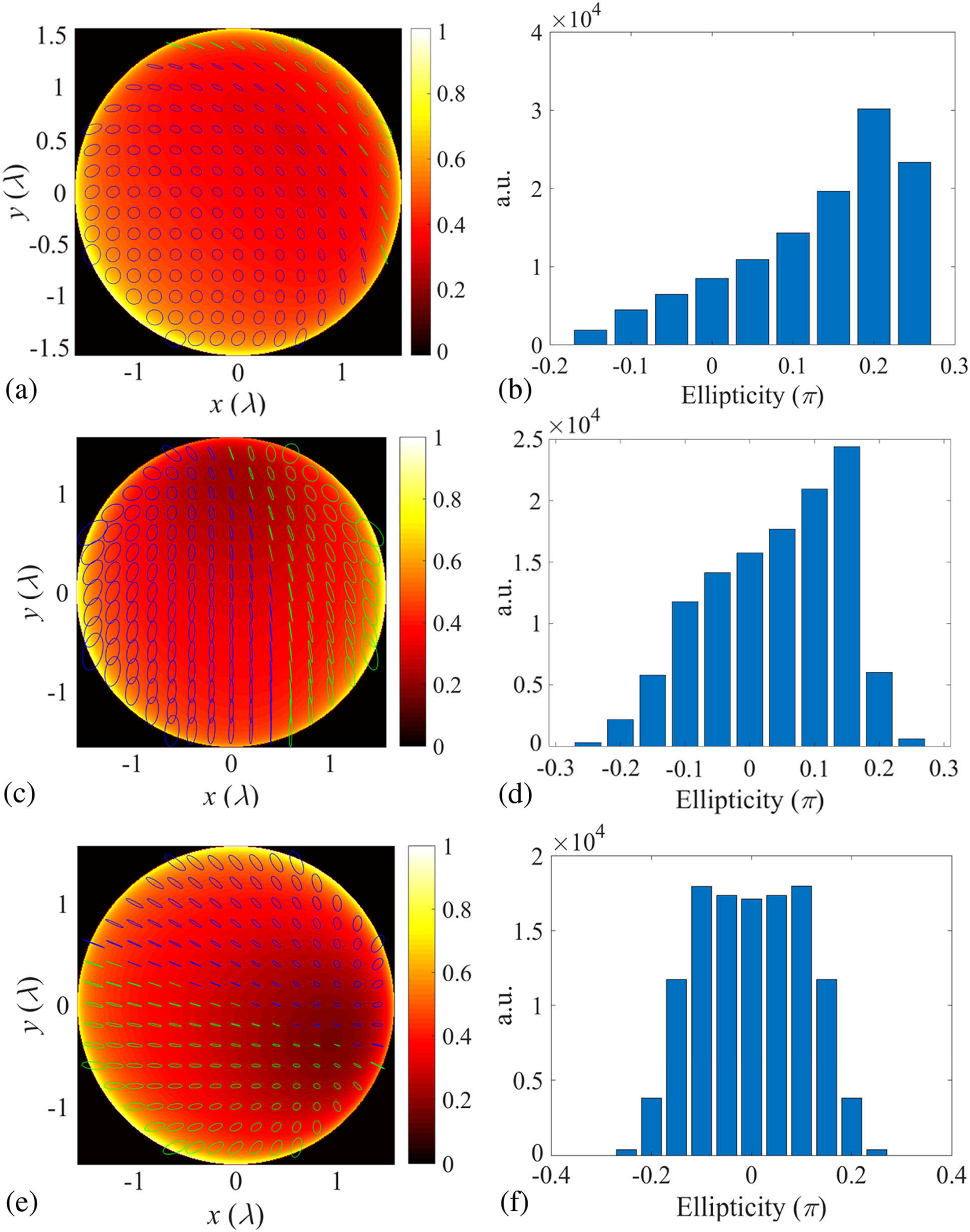
Fig. 2. (a), (c), and (e) Intensity distribution superimposed with polarization map. (b), (d), and (f) Histogram of ellipticity of the ideal incident pupil field for generating (a) photonic spin orientated along ( α , β , γ ) = ( 60 ° , 60 ° , 45 ° ) ( α , β , γ ) = ( 20 ° , 80 ° , 73 ° ) − 45 ° ( α , β , γ ) = ( 110 ° , 20 ° , 90 ° )
Fig. 3. (a) Normalized intensity distribution. (b)–(d) Stokes images. (e)–(g) Spin density distribution in the vicinity of the focus of the highly focused light given in Fig. 2(a) .
Fig. 4. (a) Normalized intensity. (b)–(d) Stokes images. (e)–(g) Spin density distribution in the vicinity of the focus of the highly focused light given in Fig. 2(c) .
Fig. 5. (a) Normalized intensity. (b)–(d) Stokes images. (e)–(g) Spin density distribution in the vicinity of the focus of the highly focused light given in Fig. 2(e) .
Fig. 6. Diagram of the experimental setup. HWP, half-wave plate; P, polarizer; BS, beam splitter; L, lens; M, mirror; SF, spatial filter.
Fig. 7. Experimental results of the (a), (c), and (e) intensity distribution with polarization map and (b), (d), and (f) histogram of ellipticity corresponding to the incident pupil field presented in Figs. 2(a) , 2(c) , and 2(e) , respectively.
Fig. 8. Spatial orientation of the spheroid.
Fig. 9. Optical force on the dielectric spheroidal particle located near the focus of the photonic spin presented in Fig. 3(a) . Equilibrium position is indicated by the asterisk.
Fig. 10. Distribution of the optical torque in the (a) x ′ – y ′ y ′ – z ′ x ′ – z ′ Θ 0 = 45 ° , ϕ 0 = 45 °
Fig. 11. Torque exerted on the spheroid at the equilibrium position versus (a) the polar angle Θ 0 ϕ 0
Fig. 12. Optical force along (a) x ′ y ′ z ′ 3(a) . Equilibrium position is indicated by the asterisk.
Fig. 13. Distribution of the optical torque in the (a) x ′ – y ′ y ′ – z ′ x ′ – z ′
Fig. 14. Particle rotation as a result of the torque from elliptically polarized light. (a) Torque and (b) rotation frequency for absorbing nanoparticles are shown as a function of Δ ϕ
| |||||||||||||||||||||||||||||||||||||||
Table 1. Theoretical and Experimental P i 2 and 7

Set citation alerts for the article
Please enter your email address
© Copyright 2018-2021 | Chinese Laser Press. All Rights Reserved 沪ICP备15018463号-20