• Photonics Research
  • Vol. 7, Issue 11, A45 (2019)
Ziv Aqua1, M. S. Kim2, and Barak Dayan1、*
Author Affiliations
  • 1AMOS and Department of Chemical and Biological Physics, Weizmann Institute of Science, Rehovot 76100, Israel
  • 2QOLS, Blackett Laboratory, Imperial College London, London SW7 2AZ, UK
  • show less
    DOI: 10.1364/PRJ.7.000A45 Cite this Article Set citation alerts
    Ziv Aqua, M. S. Kim, Barak Dayan. Generation of optical Fock and W states with single-atom-based bright quantum scissors[J]. Photonics Research, 2019, 7(11): A45 Copy Citation Text show less
    Configuration that leads to single-photon Raman interaction (SPRINT). Two optical modes, in this case orthogonal polarizations (H and V), interacting with a three-level Λ system in a single-sided cavity. Each polarization is coupled to a different “leg” of the Λ system. Upon an incident H-polarized single-photon pulse and a Λ system prepared in |gh⟩, destructive interference forces the Λ system to emit back the photon in V and undergo a Raman transition to state |gv⟩. In effect this configuration realizes a unitary swap gate between the photonic and atomic qubit.
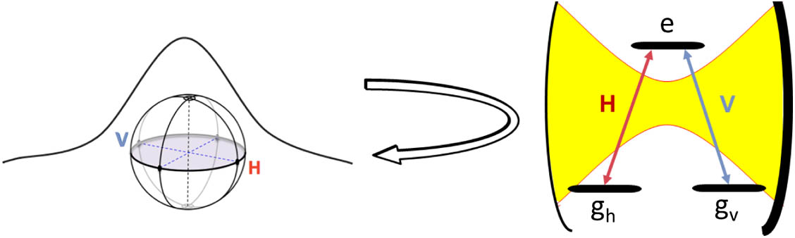
    Fig. 1. Configuration that leads to single-photon Raman interaction (SPRINT). Two optical modes, in this case orthogonal polarizations (H and V), interacting with a three-level Λ system in a single-sided cavity. Each polarization is coupled to a different “leg” of the Λ system. Upon an incident H-polarized single-photon pulse and a Λ system prepared in |gh, destructive interference forces the Λ system to emit back the photon in V and undergo a Raman transition to state |gv. In effect this configuration realizes a unitary swap gate between the photonic and atomic qubit.
    Bright quantum scissors (BQS) multi-step protocol. The protocol uses three input channels: a general H-polarized multi-photon quantum state, a V-polarized single photon, and a train of H-polarized single photons. The multi-photon pulse and the V-polarized single-photon pulse interact with the Λ system simultaneously and the resulting pulses are fed back to the system repeatedly. The H-polarized single-photon pulses are interleaved with the multi-photon pulse evolutions and reinitialize the state of the Λ system at every iteration. At the output channels of the protocol we get a train of readout single-photon pulses and a modified multi-photon state. (a) Heralded on the measurement of the nth readout photon in the V-mode, the nth-order BQS operation is applied on the input quantum state. This ensures the presence of more than n photons in the multi-photon output. For n=1, the operation amounts to a realization of the inverse annihilation. (b) Conversely, when choosing to herald on the number of photons in the multi-photon output pulse, a polarization W state manifests in the readout single-photons pulse train.
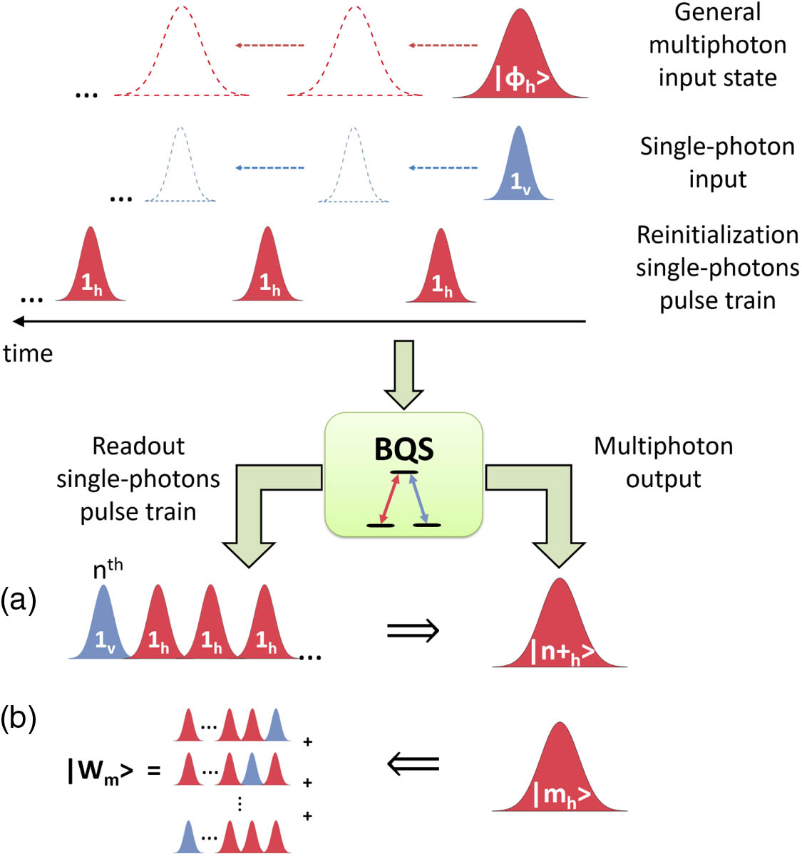
    Fig. 2. Bright quantum scissors (BQS) multi-step protocol. The protocol uses three input channels: a general H-polarized multi-photon quantum state, a V-polarized single photon, and a train of H-polarized single photons. The multi-photon pulse and the V-polarized single-photon pulse interact with the Λ system simultaneously and the resulting pulses are fed back to the system repeatedly. The H-polarized single-photon pulses are interleaved with the multi-photon pulse evolutions and reinitialize the state of the Λ system at every iteration. At the output channels of the protocol we get a train of readout single-photon pulses and a modified multi-photon state. (a) Heralded on the measurement of the nth readout photon in the V-mode, the nth-order BQS operation is applied on the input quantum state. This ensures the presence of more than n photons in the multi-photon output. For n=1, the operation amounts to a realization of the inverse annihilation. (b) Conversely, when choosing to herald on the number of photons in the multi-photon output pulse, a polarization W state manifests in the readout single-photons pulse train.
    One-dimensional atom. The effective system considered using the MOU approach in the adiabatic limit. Two modes of light, a^ω and b^ω [or A^(t) and B^(t)], interact with the two transitions of an atom in a Λ configuration.
    Fig. 3. One-dimensional atom. The effective system considered using the MOU approach in the adiabatic limit. Two modes of light, a^ω and b^ω [or A^(t) and B^(t)], interact with the two transitions of an atom in a Λ configuration.
    Optical setup suitable for the implementation of the BQS protocol. H-input and V-input are the sources for the pulses in the two modes. Switchable mirrors M1–M4 are used to repeatedly alternate between directing the readout photons to their respective outputs and rerouting the multi-photon state back into the cavity. Upon measuring a photon in the “single-photon readout V-output” on the nth iteration of the protocol, M2 is turned ON and an |n+⟩ state is measured in “multi-photon output.” On the other hand, when heralding on vacuum in the verification port and M photons in the multi-photon output, a W state is generated at the combination of single-photon readout H- and V-output.
    Fig. 4. Optical setup suitable for the implementation of the BQS protocol. H-input and V-input are the sources for the pulses in the two modes. Switchable mirrors M1–M4 are used to repeatedly alternate between directing the readout photons to their respective outputs and rerouting the multi-photon state back into the cavity. Upon measuring a photon in the “single-photon readout V-output” on the nth iteration of the protocol, M2 is turned ON and an |n+ state is measured in “multi-photon output.” On the other hand, when heralding on vacuum in the verification port and M photons in the multi-photon output, a W state is generated at the combination of single-photon readout H- and V-output.
    Pulse sequence for |ϕh⟩=|2h⟩. The H- and V-modes are represented by red and blue, respectively. Solid lines refer to pulses we send actively from H- and V-input while dotted lines represent those redirected back into the cavity. The iteration number appears above the relevant pulses.
    Fig. 5. Pulse sequence for |ϕh=|2h. The H- and V-modes are represented by red and blue, respectively. Solid lines refer to pulses we send actively from H- and V-input while dotted lines represent those redirected back into the cavity. The iteration number appears above the relevant pulses.
    Efficiency of a^−1 as a function of |α|2, the average number of photons in the initial coherent state.
    Fig. 6. Efficiency of a^1 as a function of |α|2, the average number of photons in the initial coherent state.
    nth-order BQS. Efficiency as a function of the average number of photons in the initial coherent state, |α|2. The resulting state |n+⟩ is guaranteed to have more than n photons.
    Fig. 7. nth-order BQS. Efficiency as a function of the average number of photons in the initial coherent state, |α|2. The resulting state |n+ is guaranteed to have more than n photons.
    Generation of a Fock state |3⟩ using the 3rd-order BQS. Fidelity and efficiency as functions of the average number of photons in the coherent state.
    Fig. 8. Generation of a Fock state |3 using the 3rd-order BQS. Fidelity and efficiency as functions of the average number of photons in the coherent state.
    Optical setup for Fock state generation via Bell state measurement. First, we direct the kth readout photon (either H or V) to a delay line (mirrors M5 and M6 are OFF). When the (k+1)th readout photon leaves the cavity, we turn M5 and M6 ON in order to direct it to the path with no time delay. The delay time is set such that both the kth and the (k+1)th readout photons enter the 50∶50 beam splitter simultaneously. Coincident detections at the output of the 50∶50 beam splitter guarantee that our state has collapsed on the antisymmetric Bell state [49].
    Fig. 9. Optical setup for Fock state generation via Bell state measurement. First, we direct the kth readout photon (either H or V) to a delay line (mirrors M5 and M6 are OFF). When the (k+1)th readout photon leaves the cavity, we turn M5 and M6 ON in order to direct it to the path with no time delay. The delay time is set such that both the kth and the (k+1)th readout photons enter the 50∶50 beam splitter simultaneously. Coincident detections at the output of the 50∶50 beam splitter guarantee that our state has collapsed on the antisymmetric Bell state [49].
    Efficiency of generating a Fock state |k⟩ by using an optimal coherent state input (see text).
    Fig. 10. Efficiency of generating a Fock state |k by using an optimal coherent state input (see text).
    Efficiency for generating WM states by using an initial coherent state with average photon number of 5 and applying the protocol for 10 iterations.
    Fig. 11. Efficiency for generating WM states by using an initial coherent state with average photon number of 5 and applying the protocol for 10 iterations.
    Ziv Aqua, M. S. Kim, Barak Dayan. Generation of optical Fock and W states with single-atom-based bright quantum scissors[J]. Photonics Research, 2019, 7(11): A45
    Download Citation