
Renyou Ge, Hao Li, Ya Han, Lifeng Chen, Jian Xu, Meiyan Wu, Yongqing Li, Yannong Luo, Xinlun Cai. Polarization diversity two-dimensional grating coupler on x-cut lithium niobate on insulator[J]. Chinese Optics Letters, 2021, 19(6): 060006
- Chinese Optics Letters
- Vol. 19, Issue 6, 060006 (2021)
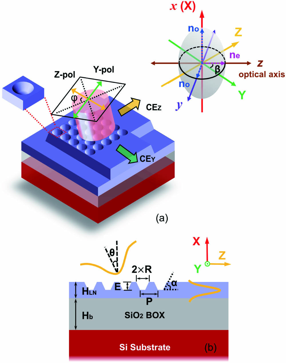
Fig. 1. (a) Schematic structure of x-cut LN 2D GCs. The angle between axis Z, Y (direction of grating) and optical axis z of LN material is β = 45°.The angle φ represents the polarization state of the fiber mode. (b) Cross-sectional view of the LN 2D GC.
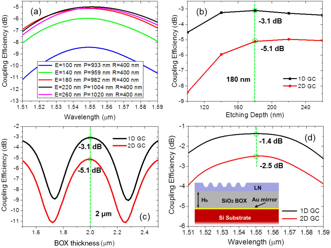
Fig. 2. (a) Coupling efficiency of the 2D GC for different structure parameters, when HLN = 360 nm, Hb = 2 µm, θ = 10°, and α = 60°. (b) The dependence of coupling efficiency and etching depth for 1D and 2D GCs at a wavelength of 1550 nm. (c) The coupling efficiency as a function of BOX thickness Hb at 1550 nm, with the parameters E = 180 nm, P = 982 nm, and R = 400 nm for the 2D GC, and E = 180 nm, P = 1.02 µm, and no = 2.21, with a duty cycle of 0.38 for uniform 1D GCs. (d) Coupling efficiency of 1D and 2D GCs with a gold mirror when Hb = 2 µm.
Fig. 3. Propagation of the coupled mode in the LN slab waveguide.
Fig. 4. (a) Coupling efficiency of CEZ, CEY, and CET as a function of the polarization angle φ. (b) Coupling spectra of CEZ, CEY, and CET when φ = 75°. (c) Relationship between the central wavelength λc and polarization angle φ.
Fig. 5. Impact of the variation of (a) etching depth ΔE, (b) grating pitch ΔP, (c) hole radius ΔR, and (d) sidewall angle Δα.
Fig. 6. (a) SEM image of LN 2D GCs. The inset shows the zoom-in picture of grating cells. (b) Optical image of the LN 2D GCs. (c) Experimental set-up scheme: TL, tunable laser; PC, polarization controller; PM, power meter.
Fig. 7. (a) Measured and calculated coupling efficiencies for the LN 1D GC and 2D GC. (b) Measured coupling efficiencies of the LN 2D GC with different hole radii.

Set citation alerts for the article
Please enter your email address
© Copyright 2018-2021 | Chinese Laser Press. All Rights Reserved 沪ICP备15018463号-20