• Photonics Research
  • Vol. 3, Issue 4, 140 (2015)
Mohamed H. El Sherif1, Mohamed H. Bakr1、*, and Ezzeldin A. Soliman2
Author Affiliations
  • 1McMaster University, Department of Electrical and Computer Engineering, Hamilton, Ontario L8S4K1, Canada
  • 2The American University in Cairo, Department of Physics, AUC Avenue, P. O. Box 74, New Cairo 11835, Egypt
  • show less
    DOI: 10.1364/PRJ.3.000140 Cite this Article Set citation alerts
    Mohamed H. El Sherif, Mohamed H. Bakr, Ezzeldin A. Soliman. E-shaped wideband plasmonic nantennas with linear and dual-linear polarizations[J]. Photonics Research, 2015, 3(4): 140 Copy Citation Text show less
    E-shape nantenna configuration: (a) side view and (b) top view.
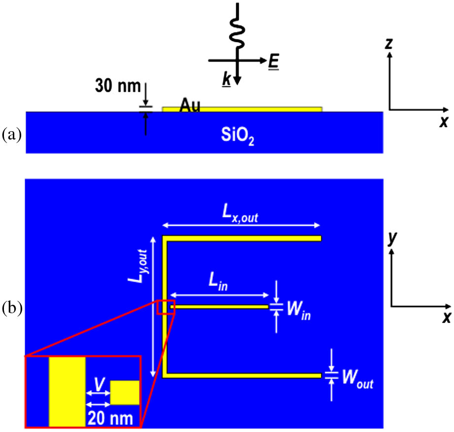
    Fig. 1. E-shape nantenna configuration: (a) side view and (b) top view.
    Excited SPPs along the arms of the E nantenna illuminated with a plane wave.
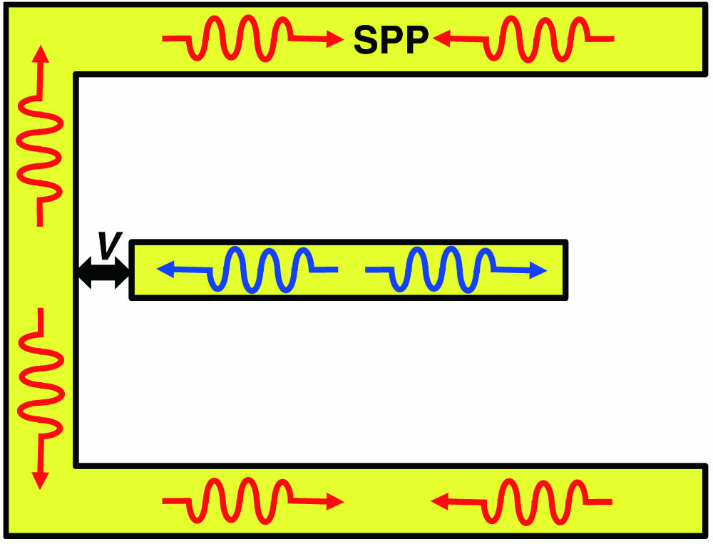
    Fig. 2. Excited SPPs along the arms of the E nantenna illuminated with a plane wave.
    Intensity enhancement at the gap of the proposed E nantenna versus wavelength.
    Fig. 3. Intensity enhancement at the gap of the proposed E nantenna versus wavelength.
    Electric field intensity distribution along the central x–y plane of the E nantenna with Lx,out=900.0 nm, Ly,out=800.0 nm, Wout=30.0 nm, Lin=550.0 nm, and Win=20.0 nm: (a) λ=2.88 μm and (b) λ=4.41 μm.
    Fig. 4. Electric field intensity distribution along the central xy plane of the E nantenna with Lx,out=900.0nm, Ly,out=800.0nm, Wout=30.0nm, Lin=550.0nm, and Win=20.0nm: (a) λ=2.88μm and (b) λ=4.41μm.
    Distribution of the magnetic field component Hz along the central x–y plane of the E nantenna with Lx,out=900.0 nm, Ly,out=800.0 nm, Wout=30.0 nm, Lin=550.0 nm, and Win=20.0 nm: (a) λ=2.88 μm and (b) λ=4.41 μm.
    Fig. 5. Distribution of the magnetic field component Hz along the central xy plane of the E nantenna with Lx,out=900.0nm, Ly,out=800.0nm, Wout=30.0nm, Lin=550.0nm, and Win=20.0nm: (a) λ=2.88μm and (b) λ=4.41μm.
    Capacitive junction coupling between the inner and outer arms.
    Fig. 6. Capacitive junction coupling between the inner and outer arms.
    S parameters describing the coupling between the inner and outer arms.
    Fig. 7. S parameters describing the coupling between the inner and outer arms.
    Extinction cross section of the E-nantenna array versus wavelength for different values of the periodicity.
    Fig. 8. Extinction cross section of the E-nantenna array versus wavelength for different values of the periodicity.
    Intensity enhancement at the nantenna gap versus wavelength for different values of the outer arm horizontal length Lx,out.
    Fig. 9. Intensity enhancement at the nantenna gap versus wavelength for different values of the outer arm horizontal length Lx,out.
    Intensity enhancement at the nantenna gap versus wavelength for different values of the outer arms vertical length Ly,out.
    Fig. 10. Intensity enhancement at the nantenna gap versus wavelength for different values of the outer arms vertical length Ly,out.
    Intensity enhancement at the nantenna gap versus wavelength for different values of outer arm width Wout.
    Fig. 11. Intensity enhancement at the nantenna gap versus wavelength for different values of outer arm width Wout.
    Intensity enhancement at the nantenna gap versus wavelength for different values of inner arm length Lin.
    Fig. 12. Intensity enhancement at the nantenna gap versus wavelength for different values of inner arm length Lin.
    Intensity enhancement at the nantenna gap versus wavelength for different values of inner arm width Win.
    Fig. 13. Intensity enhancement at the nantenna gap versus wavelength for different values of inner arm width Win.
    Dual-polarized E nantenna, where the SiO2 layer is drawn semi-transparent for better visibility: (a) side view and (b) top view.
    Fig. 14. Dual-polarized E nantenna, where the SiO2 layer is drawn semi-transparent for better visibility: (a) side view and (b) top view.
    Intensity enhancement at the two gaps of the proposed dual-polarized nantenna illuminated with normal incident plane waves: (a) y polarized and (b) x polarized.
    Fig. 15. Intensity enhancement at the two gaps of the proposed dual-polarized nantenna illuminated with normal incident plane waves: (a) y polarized and (b) x polarized.
    Mohamed H. El Sherif, Mohamed H. Bakr, Ezzeldin A. Soliman. E-shaped wideband plasmonic nantennas with linear and dual-linear polarizations[J]. Photonics Research, 2015, 3(4): 140
    Download Citation