• Journal of Infrared and Millimeter Waves
  • Vol. 40, Issue 4, 483 (2021)
Jing-Yu GUO, Ning-Jie SHI, He-Xin WANG, Yang DONG, Zhan-Liang WANG, Zhi-Gang LU, Zhao-Yun DUAN, Hua-Rong GONG, Yu-Bin GONG, and Shao-Meng WANG*
Author Affiliations
  • School of Electronic Science and Engineering, University of Electronic Scienceand Technology of China, Chengdu 610054, China
  • show less
    DOI: 10.11972/j.issn.1001-9014.2021.04.007 Cite this Article
    Jing-Yu GUO, Ning-Jie SHI, He-Xin WANG, Yang DONG, Zhan-Liang WANG, Zhi-Gang LU, Zhao-Yun DUAN, Hua-Rong GONG, Yu-Bin GONG, Shao-Meng WANG. 340 GHz folded diamond shaped waveguide slow-wave structure[J]. Journal of Infrared and Millimeter Waves, 2021, 40(4): 483 Copy Citation Text show less

    Abstract

    A folded diamond shaped waveguide slow wave structure (SWS) is proposed and investigated in this paper. Compared with the conventional folded rectangular waveguide SWS, the folded diamond shaped waveguide SWS is larger with the same frequency band, and the bandwidth is broader with the same dimension. The input-output waveguide transition structure and attenuator appropriate for this kind of SWS are put forward. Based on the proposed folded diamond shaped waveguide (FDSWG) SWS, we designed the whole SWS for a 340 GHz traveling wave tube (TWT), in which the negative phase-velocity tapering technique is adopted to improve the gain. The particle-in-cell results show that its output power and gain at 343 GHz can reach 8 w and 33 dB, respectively. Its 3-dB bandwidth is from 330 GHz to 348 GHz, with a circular electron beam of 15.3 kV and 35 mA.

    Introduction

    In recent years, researches on electromagnetic waves have been focusing on terahertz waves, which have a lot of advantages like anti-interference, high penetrability, high resolution and so on 1-2. In this context, the design of reliable terahertz radiation sources has become a key point, and the traveling wave tube is considered to be an appropriate choice. As a kind of important vacuum electron device, TWT is widely used in communication, electronic countermeasures and radar systems. The SWS, which determines the performance of the latter to a large extent, is the core component of a TWT 3-4.

    When a device’s operating frequency increases to terahertz waveband, its dimension will decrease to micro-scale. This brings greatly difficulty to manufacture 5, especially for conventional SWSs, such as microstrip line and helix. Another challenge is on heat dissipation, as the SWSs become more fragile and riskier of deformation with poor heat dissipation. Fortunately, these problems can be effectively solved by all-metal SWSs, of which folded waveguide SWS is a successful example 6-7.

    Folded waveguide (FWG) SWSs are well known for advantages of large power capacity, relatively wide bandwidth and easy microfabrication by using UV-LIGA technology 8. So far, the FWG-SWSs can mainly be divided to two categories, the first one is the conventional FWG, which is obtained by bending the rectangular waveguide along the E-plane. Besides, there are some improvements to this kind SWS, such as ridge-loaded FWG and slot-loaded FWG. Another category is the folded groove waveguide (FGWG), which has a natural tunnel for sheet beam. The groove shape can be various, such as rectangle, triangle and circle. Investigation shows that the v-shaped folded groove waveguide SWS is a kind of SWS suitable for high frequency band 9.

    Combining the advantages of FWG and FGWG SWSs, we proposed the folded diamond shaped waveguide. It employs a circular beam rather than sheet beam, as it is easier to focus for a long distance. The two sides of the waveguide are tapered to form the diamond shaped structure. This kind of SWS can work in higher frequency wave band with the same dimension of FWG SWS, and retains the advantages of the latter.

    In this paper, a FDSWG SWS operating at 340 GHz, which is the first atmospheric window with a frequency above 0.3 THz, is proposed and compared with conventional FWG in Sec. 1. In Sec. 2, the input-output couplers, attenuator, and negative phase-velocity tapering are presented. Finally, the results of beam-wave interaction and analysis of the effects of various structures proposed above are shown in Sec. 3.

    1 Model of diamond shaped waveguide SWS

    1.1 Structure of folded diamond shaped waveguide

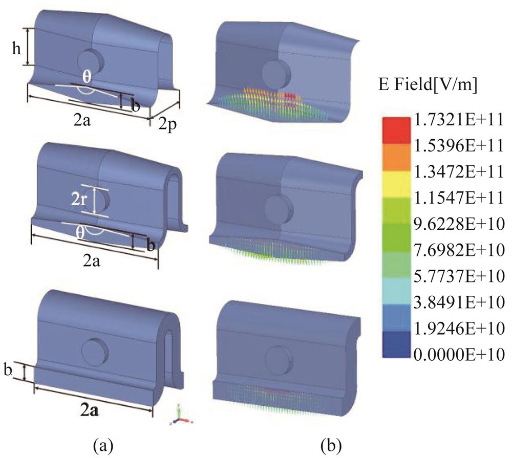
    Similar to the FWG, the FDSWG consists of bent waveguide segments and straight segments, but the cross-section is changed to diamond shape. Figure 1 shows the models and electric fields comparisons between the FWG and FDSWG SWSs. The field intensity at the center of the waveguide is higher than that at both sides, which corresponds to the position of the electron beam channel.

    Comparison between FDSWG and FWG (a) models, and (b) electric fields.

    Figure 1.Comparison between FDSWG and FWG (a) models, and (b) electric fields.

    The bending angle of bent waveguide segment is 90 degrees, and the electron beam channel is expressed as a cylinder at the center of straight segment. The structure dimensions determined by simulation are listed as following. The wide-edge length, the narrow-edge length, the direct waveguide length, the half-cycle length and the channel radius are 2abhp and r, respectively.

    1.2 Comparison of dispersion characteristics of folded diamond shaped waveguide and folded rectangular waveguide

    Dispersion characteristics and interaction impedance are important parameters for SWSs. In the process of changing the cross-section to diamond shape, the dispersion characteristics of the folded waveguide will change, as well. Figure 2 shows the dispersion curves of folded waveguide with different flare angle θ, while other dimensions are made the same. It can be seen that FDSWG SWS has higher operation frequency band, meanwhile, it fits better with the voltage line, which means that FDSWG SWS has a broader bandwidth.

    Dispersion curve of structures with different flare angle

    Figure 2.Dispersion curve of structures with different flare angle

    For the same frequency band, a 340 GHz folded rectangular waveguide is designed, and the optimized dimensions are also listed in Table 1, it’s clear that the size of folded diamond shaped waveguide is larger. Figure 3 (a) shows the dispersion curves of the 340 GHz FDSWG SWS, the 340 GHz FWG SWS and the FWG SWS with the same dimensions with the 340 GHz FDSWG SWS. The dispersion curves of the first two SWSs are both quite flat and close to each other, while the size of FDSWG SWS is larger than the FWG SWS, which confirms the assumptions of Fig. 2. The FWG SWS with the same dimensions with the 340 GHz FDSWG SWS shows a lower frequency band and a worse dispersion curve than the others. Figure 3 (b) shows that the interaction impedance of FDSWG SWS is slightly higher than that of the FWG SWS.

    ParameterValue of FWGValue of FDSWG
    2a570870
    b100100
    h230240
    p180180
    r8080

    Table 1. Structure dimensions /μm

    Comparison of FWG and FDSWG (a) dispersion characteristics, (b) interaction impedance Note: 1-FDSWG, 2-FWG with the same dimensions, 3-FWG with the same frequency band

    Figure 3.Comparison of FWG and FDSWG (a) dispersion characteristics, (b) interaction impedance Note: 1-FDSWG, 2-FWG with the same dimensions, 3-FWG with the same frequency band

    1.3 Possible effects of rounded corner

    Due to the micron size of FDSWG SWS, it might be difficult for fabrication of the sharp corner. In practical, the sharp corners may be fabricated to a rounded corner, as shown in Fig. 4, where d is the diameter of the rounded corner.

    The rounded corners of FDSWG

    Figure 4.The rounded corners of FDSWG

    We evaluated the influence of possible rounded corners on the performance of FDSWG SWS. The dispersion characteristics and interaction impedances of SWSs with different diameters of rounded corners were obtained and shown in Fig. 5. As the diameter increases, both the dispersion curves and interaction impedance curves shift towards high frequency end, while the bandwidth retains. Besides, the shift of dispersion curve will lead to the increase of synchronous voltage. The performance of the FDSWG SWS will not be affected obviously if the corner radius is kept less than 0.01mm.

    High frequency characteristics with different value of d (a) dispersion, and (b) interaction impedance.

    Figure 5.High frequency characteristics with different value of d (a) dispersion, and (b) interaction impedance.

    2 High frequency system characteristics

    For a complete SWS, the input-output coupler is indispensable. Besides, attenuators and negative phase-velocity tapering are also necessary to realize the stable high-gain operation of SWS.

    2.1 Input-output couplers

    The target for input-output couplers is to achieve the connection between the FDSWG SWS and the standard WR-2.2 waveguide (0.56 mm × 0.28 mm). As shown in Fig. 6 (a), the input-output couplers are divided into two stages, the diamond shaped waveguide is gradually converted to rectangular waveguide, and then to the standard waveguide, during which the straight waveguide segment is connected. The optimized lengths of each section are t1 = 100 μm, t2 = 600 μm, and t3 = 1 000 μm, respectively. Figure 6 (b) shows the electric field distribution on certain faces labeled in Fig. 6 (a), the field distribution in the waveguide is always TE10 mode during the two gradients.

    (a) Input-output couplers, and (b) electric field distribution on cross-sectional faces.

    Figure 6.(a) Input-output couplers, and (b) electric field distribution on cross-sectional faces.

    Figure 7 shows the S parameters of the input-output coupler. S21 is close to 0 dB, while S11 is lower than -25 dB near the operating frequency. The design index of the input-output coupler is S11 of the complete SWS. The frequency range of the standard WR-2.2 waveguide is 325∼500 GHz and the length of coupler will contribute on its S parameters. Therefore, the lowest point of S11 of the full SWS is around 390 GHz.

    S parameters of the input-output coupler

    Figure 7.S parameters of the input-output coupler

    2.2 Attenuator and sever

    Considering that the gain of SWS may be as large as 30~40 dB, the oscillation occurs usually in the case of a long simulation time, due to reflections and interaction of the beam with the backward wave. Generally speaking, approaches to suppress oscillation include using sever or attenuator to absorb the reflected wave and using phase-velocity tapering to break the synchronism between electron beam and backward wave. In addition, the phase-velocity tapering also helps to increase output power. For this FDSWG, the application of sever and attenuator is for suppressing oscillation, while the main role of phase-velocity tapering is increasing output power.

    The SWS is divided into two sections, between which attenuators are set in the severs, as shown in Fig. 8. The attenuator is made of BeO with the relative dielectric constant of 6.5 and loss tangent of 0.5 10, and the shape is designed as a pyramid with height of 0.5 mm, whose bottom is the same as the cross-section of diamond shaped waveguide. In fact, the two-section attenuator achieves better matching performance than traditional single-section attenuator with the same length, and the introduction of tapered gradients further optimizes the matching performance.

    Sketch of sever and attenuator.

    Figure 8.Sketch of sever and attenuator.

    2.3 Negative phase-velocity tapering

    Although folded waveguide is suitable for high frequency band, its interaction impedance is generally low, which is more obvious in terahertz waveband. Besides, the cathode is usually with a limited emission current density, thus the channel radius needs to be increased in order to obtain bigger cathodic current. However, the increase of channel radius will further reduce the interaction impedance. The selection of cathode current, on balance, is often unable to reach the saturation value, other measures are required to achieve high output power. Typically, negative phase-velocity tapering is an effective approach.

    When moving in the SWS, the electrons will gradually lose energy through the interaction with electromagnetic wave. When electrons reach the output end of SWS, the energy of the electron beam has been reduced to the extent that it is impossible to continue the energy-exchange between beam and wave, and then the output power reaches saturation. At this point, by reducing the phase velocity of the electromagnetic wave near the output end of SWS, the mismatched slow wave and electron beam can exchange energy again, then output power will obtain augment 11-12.

    For folded waveguide, usually the reduction of phase velocity is realized by changing the dimension. Take h, the direct waveguide length, for example, Fig. 9 shows the high frequency characteristics under different values. It can be seen that with the increase of h, the low cut-off frequency is almost unchanged, the normalized phase velocity gradually decreases, and the interaction impedance is also almost unchanged. Thus, adjusting the value of h is a viable approach to reduce the phase velocity without changing the interaction impedance.

    High frequency characteristics with different value of h (a) dispersion, and (b) interaction impedance

    Figure 9.High frequency characteristics with different value of h (a) dispersion, and (b) interaction impedance

    With negative phase-velocity tapering, the part of folded diamond shaped waveguide near the output end gets redesigned, the value of h is changed to 250 μm. For newly designed SWS, the overall structure is divided into three parts, and the period numbers are 55, 70, 18, respectively, the third one is the part for phase-velocity tapering, which is shown in Fig. 10.

    Phase-velocity of slow wave versus axial distance

    Figure 10.Phase-velocity of slow wave versus axial distance

    Finally, the ideal cylinder cathode, with a radius of 50 μm, is placed at the start plane of the SWS. Figure 11 shows the 3-D model of the complete SWS, whose background is specified as copper with relative dielectric constant of 2.2 × 10⁷ S/m 13. The transmission characteristics can be represented by the S parameters from Fig. 12. The S11 of SWS is below -20 dB from 330 to 360 GHz, which is practicable in operating band, and S21 is below -190 dB, which proves the effect of the sever and attenuator.

    3-D model of folded diamond shaped waveguide SWS.

    Figure 11.3-D model of folded diamond shaped waveguide SWS.

    S parameters for the complete SWS.

    Figure 12.S parameters for the complete SWS.

    3 Beam-wave interaction simulation

    3.1 Beam-wave interaction simulation

    The beam-wave interaction is simulated by using the CST Particle Studio 14. After optimization, the beam voltage, electric current and focusing magnetic field are set as 15.3 kV, 35 mA and 0.3 T, respectively. The signal source in terahertz waveband is generally less than 10 mW, thus the input power is optimized to 4 mW.

    As shown in Fig. 13 (a), the output signal at 343 GHz becomes stable after 0.9 ns and maintains stable for at least 20 ns, the average output power is about 8 W, which means the corresponding gain is 33 dB. Figure 13(b) shows the frequency spectrum of output signal obtained by Fast Fourier Transform, there is only one peak at the operating frequency of 343 GHz, which further proves that the potential reflected wave and higher harmonic wave are effectively suppressed.

    Output (a) signal, and (b) frequency spectrum

    Figure 13.Output (a) signal, and (b) frequency spectrum

    It can be seen from Fig. 14 that the electron beam does not diverge under the constraint of the magnetic field, and the velocity modulation occurs during the electron motion, which is more obvious near the end of the SWS. Besides, the acceleration region and deceleration region of the electron show a degree of overlap, which indicates that the output power of this period number reaches to saturation. The diagram of power versus axial distance also proves this conclusion, diagram shows that the energy-increasing curve is close to the end of the linear region.

    (a)Electron bunching, and (b)power versus axial distance

    Figure 14.(a)Electron bunching, and (b)power versus axial distance

    3.2 Effect of phase-velocity tapering

    To explain the effect of negative phase-velocity tapering, the SWS without phase-velocity tapering is also simulated. The SWS is divided into two parts only, and the numbers of cycles are 55, 80, respectively, and the output power has also reached to saturation. Figure 15 shows the electron energy distribution at 20 ns for the SWS with and without phase-velocity tapering. The initial energy of electron of two structures are both 15 300 eV, with the increase of axial distance, the electron energy shows a tapered change, that is, the energy of most electrons decreases, while that of a few electrons increases. By contrast, electrons of the SWS with negative phase-velocity tapering lose even more energy. For this SWS, the maximum decrease of electron energy is about 1 000 eV, and the energy-increase of electrons at the end is only 150 eV. Besides, near the end of SWS, there is a sudden reduction of electron energy, and the position is close to the beginning of the phase-velocity tapering part. It can be interpreted that the introduction of phase-velocity tapering further stimulates the occurrence of energy exchange, forcing more electrons to start losing energy.

    Electron kinetic energy at 20 ns.

    Figure 15.Electron kinetic energy at 20 ns.

    Figure 16 shows the comparation about output performance between the tapered and non-tapered SWSs, where the beam voltage, electric current and input power are all set as the same. As can be seen, by employing negative phase-velocity tapering technology, the maximum output power increases to 8 W from 5.7 W, and the gain increases to 33 dB, which indicates that the negative phase-velocity tapering effectively improves the output performance. The result also shows that 3-dB bandwidth is more than 18 GHz, ranging from 330 GHz to 348 GHz, which is consistent with the flat dispersion characteristics around the operating frequency described above.

    Comparation of output between two structures (a) output power, and (b) gain Note: 1-with phase-velocity tapering, 2-without phase-velocity tapering

    Figure 16.Comparation of output between two structures (a) output power, and (b) gain Note: 1-with phase-velocity tapering, 2-without phase-velocity tapering

    3.3 Comparison of operating frequency and bandwidth between FWG and FDSWG SWSs

    To verify the inference of bandwidth from Fig. 2, a FWG SWS with the same dimensions as the FDSWG SWS is designed. This SWS is divided into two segments, attenuators and input-output couplers are also set. The periods of the two segments are 40 and 80 respectively, which corresponds to the saturated output power.

    For accurately explaining the variation of bandwidth, the operating frequency are set as 274 GHz, which corresponds to the same phase of 340 GHz, the operating frequency of FDSWG, rather than the atmospheric window of this frequency band. The optimized beam voltage is 9.7 kV, the relative dielectric constant of copper is revised to 3.4 × 10⁷ S/m. The electric current, focusing magnetic field, and input power remain at 35 mA, 0.3 T and 4 mW, respectively. As shown in Fig. 17, the 3-dB bandwidth of FWG SWS with the same dimensions is about 7 GHz, ranging from 273 GHz to 280 GHz, which is only 39% of the bandwidth of the proposed FDSWG SWS. The blue dotted line shows the performance of a FWG SWS operating around 340 GHz from the Ref. [13]. As can be seen, it is with a 3-dB bandwidth of 10GHz, ranging from 336 GHz to 345 GHz, which is narrower than that of the proposed FDSWG SWS.

    Comparison of operating frequency and bandwidth

    Figure 17.Comparison of operating frequency and bandwidth

    4 Conclusion

    This paper investigates a viable terahertz slow-wave structure, i.e., a folded diamond shaped waveguide at 340 GHz, optimization and simulation are also accomplished. Compare to conventional FWG SWS, the FDSWG SWS is larger with the same frequency band, and the bandwidth is broader when dimensions are the same. In order to improve the low output power caused by limited cathode current, negative phase-velocity tapering is adopted. In addition, the input-output couplers to 340 GHz standard waveguide and pyramidal attenuator for SWS are also designed. The simulation results show that the output power of the FDSWG SWS is successfully increased to 8 W, and the corresponding gain reaches 33 dB. Another parameter, 3-dB bandwidth, reaches 18 GHz, ranges from 330 GHz to 348 GHz. All these results illustrate that the proposed FDSWG SWS is a promising scheme for terahertz waveband.

    References

    [1] P H Siegel. Terahertz technology. IEEE Transactions on Microwave Theory and Techniques, 50, 910-928(2002).

    [2] J M Chamberlain, R E Miles. New directions in terahertz technology. Ims Ind Med Surg, 38, 509-537(2009).

    [3] J H Booske, R J Dobbs, C D Joye et al. Vacuum electronic high power terahertz sources. IEEE Transactions on Terahertz Science and Technology, 1, 54-75(2011).

    [4] T W Crowe. Multiplier technology for terahertz applications, 58-61(1998).

    [5] A Xu, Y J Wang, S M Yan et al. Design and analysis for 0.41 THz folded waveguide slow wave structure. Journal of Terahertz Science and Electron Information Technologv, 12, 798-803(2014).

    [6] R K Sharmaet, A K Sharma, B D Pant et al. 6: Design and development of 100 GHz folded waveguide TWT, 505-506(2010).

    [7] X W Bian, M Miao, Z S Li. Design and analysis of micro-machined folded waveguide slow-wave structure for 220 GHz application, 1-4(2016).

    [8] R L Ives. Microfabrication of high-frequency vacuum electron devices. IEEE Transactions on Plasma Science, 32, 1277-1291(2004).

    [9] Y Tian, L Yue, Q Zhou et al. Investigation on sheet beam folded V-shape groove waveguide for millimeter-wave TWT. IEEE Transactions on Plasma Science, 44, 1363-1368(2016).

    [10] H.X WANG, Z L WANG, X Y Li et al. Study of a miniaturized dual-beam TWT with planar dielectric-rods-support uniform metallic meander line. Physics of Plasmas, 25, 063113(2018).

    [11] S S Jung, A V Soukhov, B Jia et al. Efficiency enhancement and harmonic reduction of wideband helix traveling-wave tubes with positive phase velocity tapering. Japanese Journal of Applied Physics, 41, 4007-4013(2002).

    [12] W Q Lei, Y Jiang, L L Hu et al. Optimization design of high efficiency in 140 GHz folded waveguide slow wave structure, 782-78(2016).

    [13] L Yao, J Yao, Z Yang et al. A 0.34-THz high-power, slow-wave structure: designing and microfabricating an H-plane ridge-loaded folded waveguide. IEEE Nanotechnology Magazine, 13, 35-42(2019).

    [14] CST computer simulation technology AG . CST studio suite 2017. https://www.cst.com

    Jing-Yu GUO, Ning-Jie SHI, He-Xin WANG, Yang DONG, Zhan-Liang WANG, Zhi-Gang LU, Zhao-Yun DUAN, Hua-Rong GONG, Yu-Bin GONG, Shao-Meng WANG. 340 GHz folded diamond shaped waveguide slow-wave structure[J]. Journal of Infrared and Millimeter Waves, 2021, 40(4): 483
    Download Citation