- Infrared and Laser Engineering
- Vol. 49, Issue 7, 20190433 (2020)
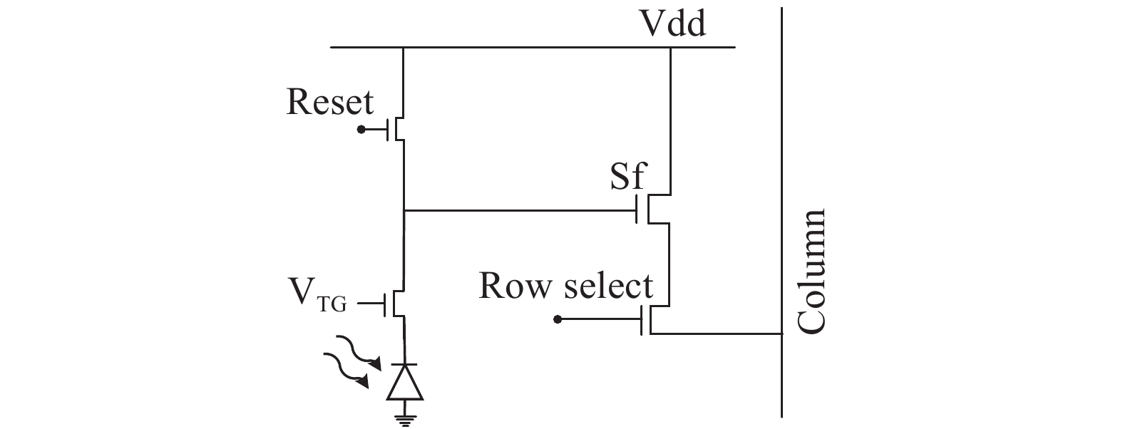
Fig. 1. 4T pixel unit schematic
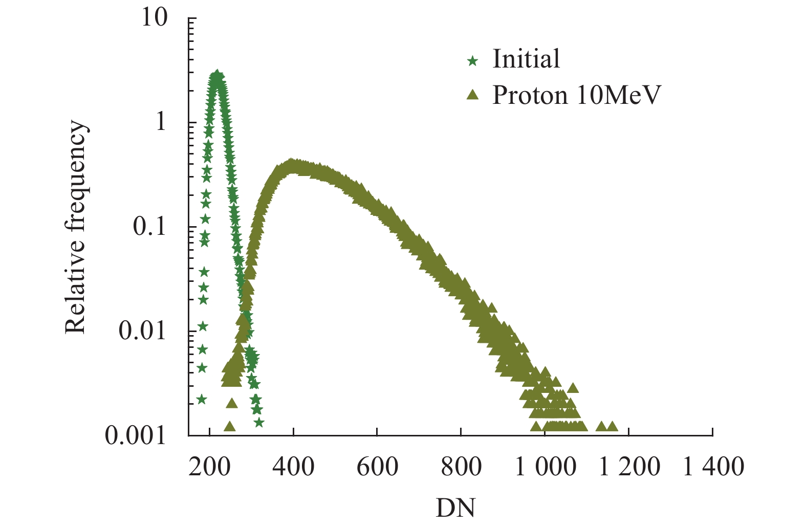
Fig. 2. Comparison of the dark signal distribution between devices proton pre-and post-irradiation
Fig. 3. Dark signal defect diagram after being irradiated by proton
Fig. 4. 3D figure of dark signal hot pixel before radiation (a) and after radiation (b)
Fig. 5. Proton-induced single event transient bright spot
Fig. 6. Proton-induced single event transient bright cluster (a) and different shape bright lines (b), (c), (d)

Download Citation

Set citation alerts for the article
Please enter your email address
© Copyright 2018-2021 | Chinese Laser Press. All Rights Reserved 沪ICP备15018463号-20