
Bin Zhuang, Chengfang Xu, Yi Geng, Guangzhi Zhao, Hui Chen, Zhengquan He, Zhaoxin Wu, Liyong Ren. Round-trip imaging through scattering media based on optical transmission matrix[J]. Chinese Optics Letters, 2018, 16(4): 041102
- Chinese Optics Letters
- Vol. 16, Issue 4, 041102 (2018)
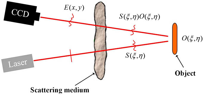
Fig. 1. Schematic of the round-trip imaging through a scattering medium.
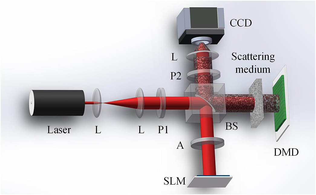
Fig. 2. Experimental setup. Scattering medium (Thorlabs Optics 220 grit ground-glass diffuser); DMD, digital micromirror devices (ViALUX, V-7001VIS, 1024 pixel × 768 pixel 2048 pixel × 2048 pixel 2048 pixel × 1536 pixel
Fig. 3. Typical measured T ( x , y ; ξ , η )
Fig. 4. Reconstruction of the object constructed by DMD. (a) A binary amplitude object constructed by using DMD. (b) Output speckle image of the object captured by CCD. (c) Interference image of the object wave and the reference wave. (d), (e) Amplitude and phase of E ( x , y )
Fig. 5. Reconstruction of the real target object. (a) USAF 1951 test pattern. (b) Output speckle image of the object. (c) Recovered object. Scale bars indicate 300 μm in (a), (c) and 2000 μm in (b).
Fig. 6. (a) Speckle pattern of the illumination wave. (b) Object constructed using the DMD. (c) Intensity of the reflected wave of the object. Scale bar: 1000 μm.

Set citation alerts for the article
Please enter your email address
© Copyright 2018-2021 | Chinese Laser Press. All Rights Reserved 沪ICP备15018463号-20