• Journal of Infrared and Millimeter Waves
  • Vol. 40, Issue 4, 547 (2021)
Ya-Min ZHANG1、2, Hong-Ming FEI1、2、*, Han LIN3, Yu-Hui Han1、2, Ming-Da ZHANG1、2, Xue-Mei LI1、2, and Yi-Biao YANG1、2
Author Affiliations
  • 1Department of Physics and Optoelectronics, Taiyuan University of Technology, Taiyuan 030024, China
  • 2Key Laboratory of Advanced Transducers and Intelligent Control System, Ministry of Education, Taiyuan University of Technology, Taiyuan 030024, China
  • 3Centre for Translational Atomaterials, Swinburne University of Technology, Victoria 3122, Australia
  • show less
    DOI: 10.11972/j.issn.1001-9014.2021.04.014 Cite this Article
    Ya-Min ZHANG, Hong-Ming FEI, Han LIN, Yu-Hui Han, Ming-Da ZHANG, Xue-Mei LI, Yi-Biao YANG. Design of all-dielectric valley photonic crystals with low symmetry elliptical lattice[J]. Journal of Infrared and Millimeter Waves, 2021, 40(4): 547 Copy Citation Text show less
    (a) Schematic diagram of all-dielectric valley photonic crystal structure based on elliptical lattice. Silicon and silicon dioxide are gray and blue, respectively. The incident light enters from the left waveguide, propagates along the valley photonic crystal waveguide (red) with valley Hall effect, and exits from the right waveguide, (b) Schematic diagram of unit cell structure of the valley photonic crystal VPC‖+ , (c) Photonic band structure of TE mode of VPC‖ and VPC‖+ , (d) Photonic band structure of TE mode of VPC⊥ and VPC⊥+, (e) The electric field intensity distributions of left-handed circular polarized (LCP) and right-handed circular polarized (RCP) light sources in the center of the dielectric column in VPC‖+ , where LCP light propagates along the K direction, while RCP light propagates along the K’ direction, (f) The electric field intensity distributions of left-handed circular polarized (LCP) and right-handed circular polarized (RCP) light sources in the center of the dielectric column in VPC⊥+ , where LCP light propagates along the K direction, while RCP light propagates along the K’ direction. The directions of K and K’ in the figure are indicated by white arrows.
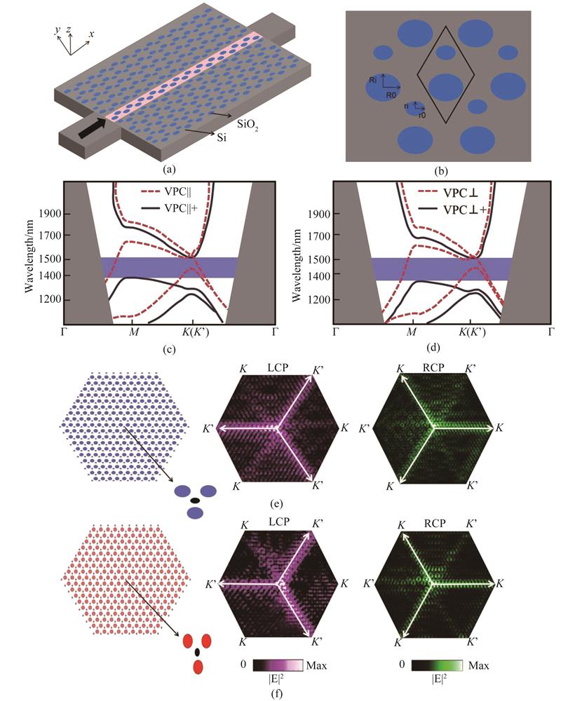
    Fig. 1. (a) Schematic diagram of all-dielectric valley photonic crystal structure based on elliptical lattice. Silicon and silicon dioxide are gray and blue, respectively. The incident light enters from the left waveguide, propagates along the valley photonic crystal waveguide (red) with valley Hall effect, and exits from the right waveguide, (b) Schematic diagram of unit cell structure of the valley photonic crystal VPC‖+ , (c) Photonic band structure of TE mode of VPC‖ and VPC‖+ , (d) Photonic band structure of TE mode of VPC⊥ and VPC⊥+, (e) The electric field intensity distributions of left-handed circular polarized (LCP) and right-handed circular polarized (RCP) light sources in the center of the dielectric column in VPC‖+ , where LCP light propagates along the K direction, while RCP light propagates along the K’ direction, (f) The electric field intensity distributions of left-handed circular polarized (LCP) and right-handed circular polarized (RCP) light sources in the center of the dielectric column in VPC⊥+ , where LCP light propagates along the K direction, while RCP light propagates along the K’ direction. The directions of K and K’ in the figure are indicated by white arrows.
    (a) The supercell structure composed of VPC‖+ and VPC‖-. The upper and lower sides are four periods of VPC‖+ and VPC‖-, (b) The photonic band diagram of the supercell structure composed of VPC‖+ and VPC‖-, (c) The electric field intensity distributions of LCP and RCP light sources placed at the center of the supercell structure (the interface between VPC‖+ and VPC‖-), respectively, (d) The supercell structure composed of VPC⊥+ and VPC⊥-. The upper and lower sides are four periods of VPC⊥+ and VPC⊥-, (e) The photonic band diagram of the supercell structure composed of VPC⊥+ and VPC⊥-, (f) The electric field intensity distributions of LCP and RCP light sources placed at the center of the supercell structure (the interface between VPC⊥+ and VPC⊥-), respectively, (g) Plots of forward and backward transmittance of the structure composed of VPC‖+ and VPC‖-, and the contrast ratio, (h) Plots of forward and backward transmittance of the structure composed of VPC⊥+ and VPC⊥-, and the contrast ratio
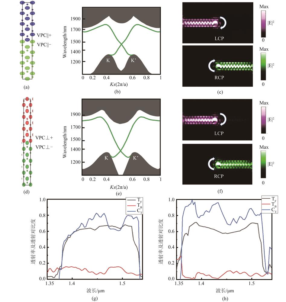
    Fig. 2. (a) The supercell structure composed of VPC‖+ and VPC‖-. The upper and lower sides are four periods of VPC‖+ and VPC‖-, (b) The photonic band diagram of the supercell structure composed of VPC‖+ and VPC‖-, (c) The electric field intensity distributions of LCP and RCP light sources placed at the center of the supercell structure (the interface between VPC‖+ and VPC‖-), respectively, (d) The supercell structure composed of VPC⊥+ and VPC⊥-. The upper and lower sides are four periods of VPC⊥+ and VPC⊥-, (e) The photonic band diagram of the supercell structure composed of VPC⊥+ and VPC⊥-, (f) The electric field intensity distributions of LCP and RCP light sources placed at the center of the supercell structure (the interface between VPC⊥+ and VPC⊥-), respectively, (g) Plots of forward and backward transmittance of the structure composed of VPC‖+ and VPC‖-, and the contrast ratio, (h) Plots of forward and backward transmittance of the structure composed of VPC⊥+ and VPC⊥-, and the contrast ratio
    (a) An Ω-shape topological optical waveguide composed of VPC‖+ and VPC‖-, and the electric field intensity distributions of light propagating along the Ω-shape optical waveguide, (b) A straight topological optical waveguide composed of VPC‖+ and VPC‖-, and the electric field intensity distributions along the straight topological optical waveguide, (c) A straight topological optical waveguide with a point defect, and the electric field intensity distributions of light propagating along the defective waveguide, (d) An Ω-shape topological optical waveguide composed of VPC⊥+ and VPC⊥-, and the electric field intensity distributions of light propagating along the Ω-shape optical waveguide, (e) A straight topological optical waveguide composed of VPC⊥+ and VPC⊥-, and the electric field intensity distributions along the straight topological optical waveguide, (f) A straight topological optical waveguide with a point defect, and the electric field intensity distributions of light propagating along the defective waveguide. The point defects are marked by the rectangle, (g) Plots of the forward transmittance of the topological optical waveguide composed of VPC‖+ and VPC‖-. Ω-shape (red), straight waveguide (blue) and defective waveguide (black). The gray area represents the wavelength region of the photonic bandgap, (h) Plots of the forward transmittance of the topological optical waveguide composed of VPC⊥+ and VPC⊥-. Ω-shape (red), straight waveguide (blue) and defective waveguide (black). The gray area represents the wavelength region of the photonic bandgap, (i) Forward transmittance plots of the Ω-shaped waveguide composed of VPC‖+ and VPC‖- and composed of VPC⊥+ and VPC⊥-, respectively, for comparison.
    Fig. 3. (a) An Ω-shape topological optical waveguide composed of VPC‖+ and VPC‖-, and the electric field intensity distributions of light propagating along the Ω-shape optical waveguide, (b) A straight topological optical waveguide composed of VPC‖+ and VPC‖-, and the electric field intensity distributions along the straight topological optical waveguide, (c) A straight topological optical waveguide with a point defect, and the electric field intensity distributions of light propagating along the defective waveguide, (d) An Ω-shape topological optical waveguide composed of VPC⊥+ and VPC⊥-, and the electric field intensity distributions of light propagating along the Ω-shape optical waveguide, (e) A straight topological optical waveguide composed of VPC⊥+ and VPC⊥-, and the electric field intensity distributions along the straight topological optical waveguide, (f) A straight topological optical waveguide with a point defect, and the electric field intensity distributions of light propagating along the defective waveguide. The point defects are marked by the rectangle, (g) Plots of the forward transmittance of the topological optical waveguide composed of VPC‖+ and VPC‖-. Ω-shape (red), straight waveguide (blue) and defective waveguide (black). The gray area represents the wavelength region of the photonic bandgap, (h) Plots of the forward transmittance of the topological optical waveguide composed of VPC⊥+ and VPC⊥-. Ω-shape (red), straight waveguide (blue) and defective waveguide (black). The gray area represents the wavelength region of the photonic bandgap, (i) Forward transmittance plots of the Ω-shaped waveguide composed of VPC‖+ and VPC‖- and composed of VPC⊥+ and VPC⊥-, respectively, for comparison.
    Ya-Min ZHANG, Hong-Ming FEI, Han LIN, Yu-Hui Han, Ming-Da ZHANG, Xue-Mei LI, Yi-Biao YANG. Design of all-dielectric valley photonic crystals with low symmetry elliptical lattice[J]. Journal of Infrared and Millimeter Waves, 2021, 40(4): 547
    Download Citation