• Acta Optica Sinica
  • Vol. 40, Issue 15, 1522001 (2020)
Hanqing Zheng, Qingfeng Cui*, Yang Hu, Lin Sun, Xudong Gao, and Yu Guo
Author Affiliations
  • School of Opto-Electronic Engineering, Changchun University of Science and Technology, Changchun, Jilin 130022, China
  • show less
    DOI: 10.3788/AOS202040.1522001 Cite this Article Set citation alerts
    Hanqing Zheng, Qingfeng Cui, Yang Hu, Lin Sun, Xudong Gao, Yu Guo. Method for Expanding Field-of-View of Cassegrain System with Computational Imaging[J]. Acta Optica Sinica, 2020, 40(15): 1522001 Copy Citation Text show less
    Relationship between contributions of coma and astigmatism to diffuse spot and field of view
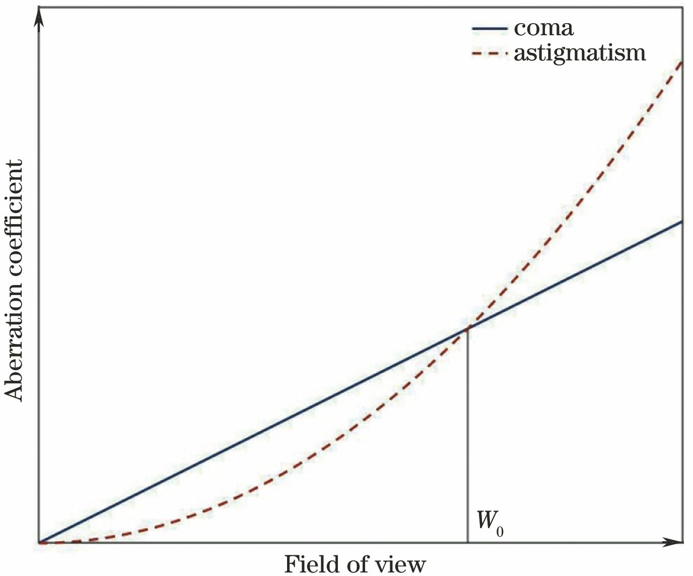
    Fig. 1. Relationship between contributions of coma and astigmatism to diffuse spot and field of view
    Flow chart of proposed method
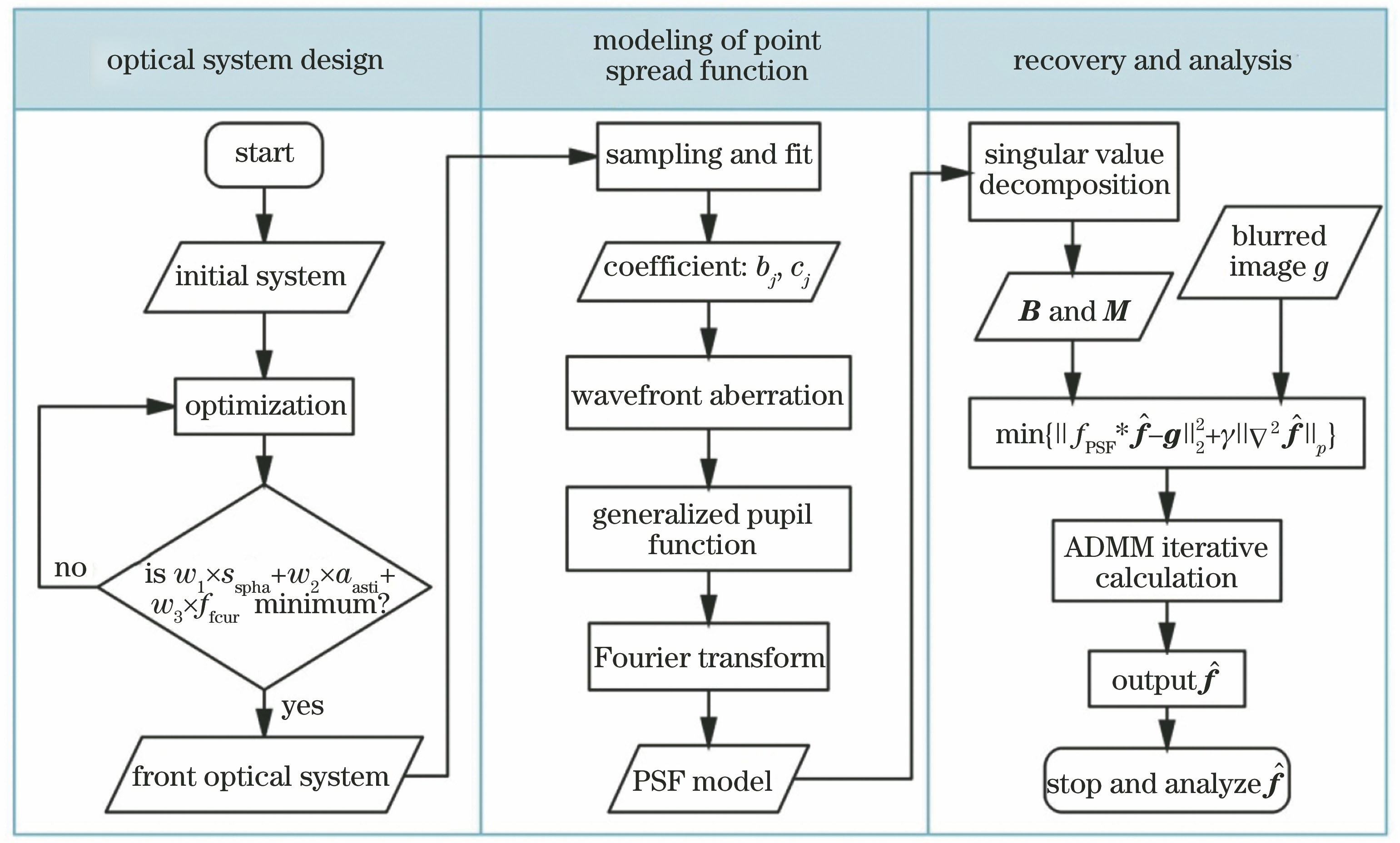
    Fig. 2. Flow chart of proposed method
    Layout of designed optical system
    Fig. 3. Layout of designed optical system
    Wavefront aberration at each field of view. (a)(b) 0°; (c)(d) 0.38°; (e)(f) 0.53°; (g)(h) 0.75°
    Fig. 4. Wavefront aberration at each field of view. (a)(b) 0°; (c)(d) 0.38°; (e)(f) 0.53°; (g)(h) 0.75°
    Diffuse spot at each field of view. (a)(b) 0°; (c)(d) 0.38°; (e)(f) 0.53°; (g)(h) 0.75°
    Fig. 5. Diffuse spot at each field of view. (a)(b) 0°; (c)(d) 0.38°; (e)(f) 0.53°; (g)(h) 0.75°
    PSF comparison results of different models. (a) PSF calculated by Zemax software; (b) PSF calculated by proposed model
    Fig. 6. PSF comparison results of different models. (a) PSF calculated by Zemax software; (b) PSF calculated by proposed model
    Comparison of results before and after simulated imaging restoration. (a)(c) Simulated image and its partial enlarged view; (b)(d) restoration image and its partial enlarged view
    Fig. 7. Comparison of results before and after simulated imaging restoration. (a)(c) Simulated image and its partial enlarged view; (b)(d) restoration image and its partial enlarged view
    Comparison of results before and after imaging restoration of resolution plate. (a)(c)(e) Simulation image of resolution plate and its partial enlarged views; (b)(d)(f) restoration image and its partial enlarged views
    Fig. 8. Comparison of results before and after imaging restoration of resolution plate. (a)(c)(e) Simulation image of resolution plate and its partial enlarged views; (b)(d)(f) restoration image and its partial enlarged views
    MTF comparison of each region in Fig. 8 before and after restoration. (a) MTF of each region before restoration; (b) MTF of each region after restoration
    Fig. 9. MTF comparison of each region in Fig. 8 before and after restoration. (a) MTF of each region before restoration; (b) MTF of each region after restoration
    TermZernike polynomialName
    Z001Piston
    Z11Rcos θX-tilt
    Z1-1Rsin θY-tilt
    Z202R2-1Defocus
    Z22R2cos(2θ)0° astigmatism
    Z2-2R2sin(2θ)45° astigmatism
    Z31(3R3-2R)cos θX-coma
    Z3-1(3R3-2R)sin θY-coma
    Z406R4-6R2+1Sphere
    Table 1. First nine terms of fringe Zernike polynomial
    ParameterContent
    Focal length /mm470
    F-number5.5
    Wavelength /nm900--1700
    Field of view /(°)1.5
    Table 2. Design specifications of system
    jY fieldbjcj
    100.00840.0034
    20.0390.22830.0986
    30.0940.55320.2635
    40.1881.12320.5525
    50.2811.66020.8045
    60.3752.21991.0885
    70.4692.75481.3410
    80.5633.28611.6002
    90.6563.83261.8374
    100.7504.38082.1167
    Table 3. Fitting coefficients for sampling points
    Hanqing Zheng, Qingfeng Cui, Yang Hu, Lin Sun, Xudong Gao, Yu Guo. Method for Expanding Field-of-View of Cassegrain System with Computational Imaging[J]. Acta Optica Sinica, 2020, 40(15): 1522001
    Download Citation