• Infrared and Laser Engineering
  • Vol. 52, Issue 9, 20230115 (2023)
Xiangxiang Meng1, Han Shang1, Mingrui Xin2、*, Xudong Wang3, and Mingjie Qiu1
Author Affiliations
  • 1School of Physics and Electronic Information, Yantai University, Yantai 264005, China
  • 2School of Information Science and Engineering, Harbin Institute of Technology, Weihai, Weihai 264209, China
  • 3Military Science Systems Engineering Research Institute, Beijing 102300, China
  • show less
    DOI: 10.3788/IRLA20230115 Cite this Article
    Xiangxiang Meng, Han Shang, Mingrui Xin, Xudong Wang, Mingjie Qiu. Development of emission optical system for laser wireless power transmission[J]. Infrared and Laser Engineering, 2023, 52(9): 20230115 Copy Citation Text show less
    (a) Gaussian optics of collimator lens; (b) Gaussian optics of imaging lens
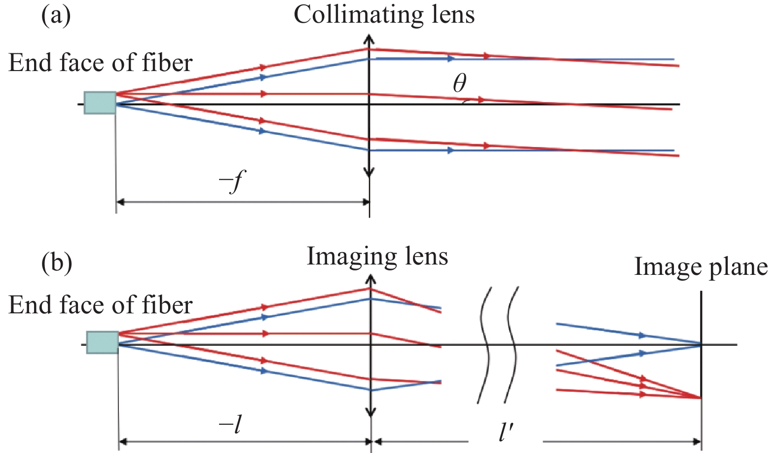
    Fig. 1. (a) Gaussian optics of collimator lens; (b) Gaussian optics of imaging lens
    (a) Design results of 500 m image distance; (b) Focusing effect from different fields at 500 m
    Fig. 2. (a) Design results of 500 m image distance; (b) Focusing effect from different fields at 500 m
    (a) Wavefront aberration of wavelength 808 nm; (b) Wavefront aberration of wavelength 632.8 nm
    Fig. 3. (a) Wavefront aberration of wavelength 808 nm; (b) Wavefront aberration of wavelength 632.8 nm
    Optical fiber end face movement at different focusing distances
    Fig. 4. Optical fiber end face movement at different focusing distances
    Comparison of wavefront aberration of two design methods after focusing
    Fig. 5. Comparison of wavefront aberration of two design methods after focusing
    (a) Spot at 200 m with fiber core of 600 μm×600 μm; (b) Spot at 1 km with fiber core of 200 μm×200 μm
    Fig. 6. (a) Spot at 200 m with fiber core of 600 μm×600 μm; (b) Spot at 1 km with fiber core of 200 μm×200 μm
    (a) Unfocused spot at 200 m; (b) Unfocused spot at 300 m; (c) Focused spot at 200 m; (d) Focused spot at 300 m
    Fig. 7. (a) Unfocused spot at 200 m; (b) Unfocused spot at 300 m; (c) Focused spot at 200 m; (d) Focused spot at 300 m
    Three-dimensional model of laser emission optical system
    Fig. 8. Three-dimensional model of laser emission optical system
    (a) Developed laser emission optical system; (b) Installed on rotational platform
    Fig. 9. (a) Developed laser emission optical system; (b) Installed on rotational platform
    Test result of wavefront aberration RMS
    Fig. 10. Test result of wavefront aberration RMS
    ParameterSpecification
    Wavelength/nm808 & 632.8
    Focal length/mm550
    Aperture/mm≥240
    Optical length/mm≤660
    Focusing range/m200-1000
    Table 1. Design parameters of laser emission optical system
    Xiangxiang Meng, Han Shang, Mingrui Xin, Xudong Wang, Mingjie Qiu. Development of emission optical system for laser wireless power transmission[J]. Infrared and Laser Engineering, 2023, 52(9): 20230115
    Download Citation