
Fei Chen, Qinghua Gui. Non-Gap Loss of Compound Parabolic Concentrator with Solar Vacuum Tube as Absorber[J]. Acta Optica Sinica, 2022, 42(2): 0208001
- Acta Optica Sinica
- Vol. 42, Issue 2, 0208001 (2022)
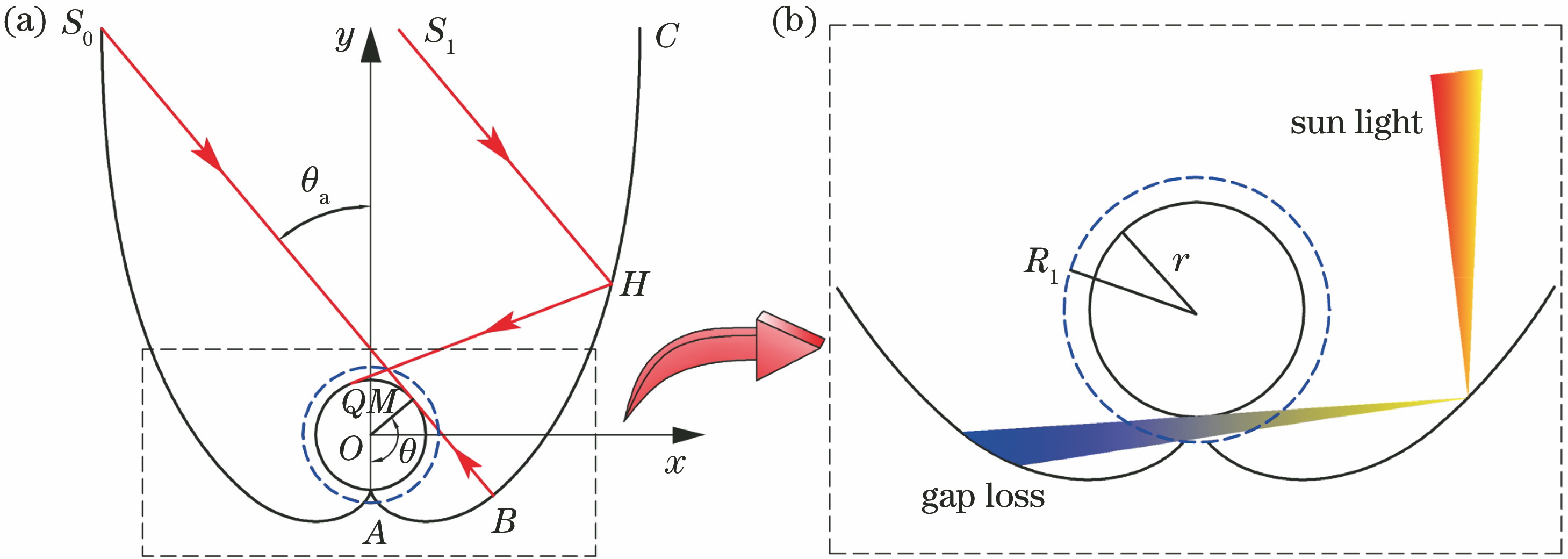
Fig. 1. Model diagram and gap loss of S-CPC. (a) Cross-sectional view of physical model; (b) gap loss of S-CPC
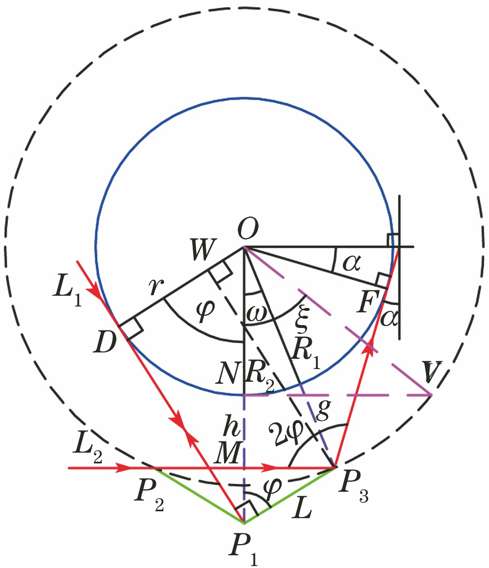
Fig. 2. Construction of equal-length reflector
Fig. 3. Construction of reflective surface
Fig. 4. Physical model of CPC without gap loss
Fig. 5. Calculation flow chart of program
Fig. 6. 3D printing of CPC model without gap loss
Fig. 7. Laser verification experimental platform. (a) Schematic diagram of experimental platform; (b) physical picture of experimental platform
Fig. 8. Error analysis diagram of different incident angles
Fig. 9. Error analysis diagram of different incident positions. (a) Incident angle of 0°; (b) incident angle of 10°; (c) incident angle of 20°; (d) incident angle of 30°
Fig. 10. Structure of equal-length reflector. (a) Single pair of reflectors; (b) two pairs of reflectors; (c) three pairs of reflectors; (d) four pairs of reflectors; (e) five pairs of reflectors; (f) six pairs of reflectors
Fig. 11. Single side length of equal-length reflector
Fig. 12. Relationship between absorber radius and gap size
Fig. 13. Relationship between different angles
Fig. 14. Concentrating characteristics of equal-length reflector of CPC without gap loss. (a) Single pair of reflectors; (b) three pairs of reflectors; (c) five pairs of reflectors
Fig. 15. Visual optical performance of CPC without gap loss. (a) Incident angle of 15°; (b) incident angle of 40°; (c) incident angle of 50°

Set citation alerts for the article
Please enter your email address
© Copyright 2018-2021 | Chinese Laser Press. All Rights Reserved 沪ICP备15018463号-20