
Hui Li, Xiaobin Wu, Xiaoquan Han, He Ma, Pengfei Sha. Lithography Illumination System Based on Fourier Synthesis Technology[J]. Chinese Journal of Lasers, 2023, 50(6): 0605003
- Chinese Journal of Lasers
- Vol. 50, Issue 6, 0605003 (2023)
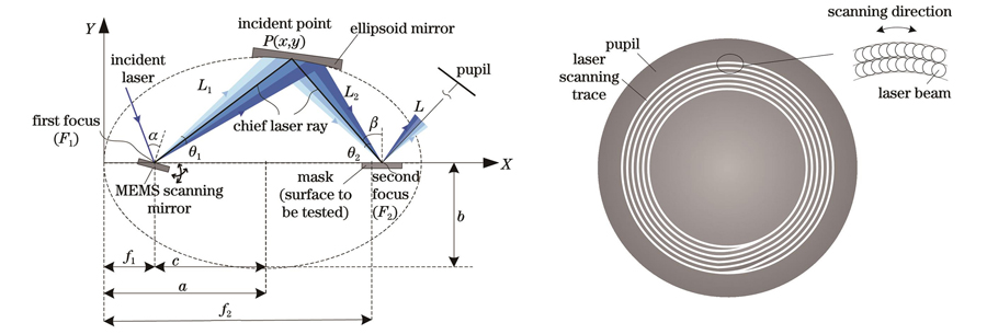
Fig. 1. Schematic diagrams of Fourier-synthesis illuminator. (a) Schema of ellipsoid mirror imaging; (b) scan track of circle illumination on pupil plane
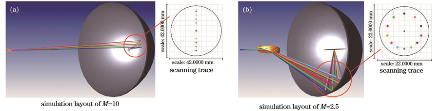
Fig. 2. Simulation model of ray path of reflective Fourier-synthesis illuminator based on MEMS mirror. (a) M=10; (b) M=2.5
Fig. 3. Spot diagrams of all scanning multi-configuration on image surface. (a) M=10; (b) M=2.5
Fig. 4. Simulation of illumination patterns formed by MEMS mirror angle scanning. (a) Illumination point when MEMS mirror is not rotated; (b) dipole illumination; (c) annular illumination; (d)-(e) quadrupole illumination (different spacings)
Fig. 5. Visible light experimental setup for Fourier-synthesis illuminator. (a) Schematic diagram; (b) photograph
Fig. 6. Illumination patterns for ellipsoidal mirror imaging tested by beam profiling system. (a) Initial laser spot; (b)-(d) disk illumination; (e)-(h) annular illumination; (i)-(l) dipole illumination; (m)-(p) quadrupole illumination
Fig. 7. Illumination size on ellipsoidal mirror focus tested by beam profiling system. (a) Initial laser beam size; (b) image size of ellipsoidal mirror with M=2.5; (c) image size of ellipsoidal mirror with M=10

Set citation alerts for the article
Please enter your email address
© Copyright 2018-2021 | Chinese Laser Press. All Rights Reserved 沪ICP备15018463号-20