
A. Tentori, A. Colaïtis, D. Batani. 3D Monte-Carlo model to study the transport of hot electrons in the context of inertial confinement fusion. Part I[J]. Matter and Radiation at Extremes, 2022, 7(6): 065902
- Matter and Radiation at Extremes
- Vol. 7, Issue 6, 065902 (2022)
Abstract
I. INTRODUCTION
In the direct drive1,2 and shock ignition (SI)3–5 approaches to inertial confinement fusion (ICF), laser intensities up to 1015–1016 W/cm2 are envisaged to bring the hotspot to the required conditions. In the standard direct drive scheme, the laser intensity rises following an adiabat shaping,6 whereas in SI, a high-intensity spike launches a strong converging shock after the compression phase. Because of the high intensities, when the laser light couples with the plasma created by the compression beams, several processes responsible for the generation of suprathermal electrons, so-called “hot electrons,” take place. Of particular note among these processes are stimulated Raman scattering (SRS) and two-plasmon decay (TPD), which excite electron plasma waves (EPWs) around nc/4.7–9 Resonant absorption (RAB) of laser light can also excite EPWs around the critical density.
In the last decade, several numerical and experimental investigations have been conducted with the aim of understanding the influence of hot electrons on implosion performance, considering both the standard direct drive and the SI approaches to ICF.10–14 These studies agree in showing that too-energetic electrons can propagate through the capsule and preheat the DT shell, changing the hydrodynamic conditions of the hotspot and jeopardizing ignition. While in the standard direct drive approach, the presence of hot electrons is deleterious, in SI, their generation is driven by the high-intensity laser spike after the compression phase. Hence, if the target areal density is sufficiently high and if hot electrons have low kinetic energy, they are stopped in the outer part of the shell and the preheating effect is limited. It is therefore important to develop numerical tools that enable accurate evaluation of the effects of hot electrons on implosion schemes.
Currently, with the increased computational power that has become available, 3D hydrodynamic codes are being developed and, with them, has arisen the need to include 3D hot electron transport modules. We report here on a 3D Monte-Carlo (MC) method to simulate hot-electron propagation in ionized fusion targets, with the aim of future implementation in hydrodynamic codes. We consider a “mixed” algorithm15–17 in which “soft” collisions are described according to multiple-scattering theories, while “hard” collisions are simulated individually, i.e., by considering two-body interaction. These algorithms are implemented in widely used MC codes such as Geant418 and Penelope.17,19,20 Once it has been implemented in hydrodynamic codes, this model will be particularly useful to investigate the role of hot electrons in ICF, allowing the development of robust implosion schemes. Furthermore, it will be used to interpret experiments aimed at investigating the role and characteristics of hot electrons, without relying on “cold” MC codes. It should be noticed that an analysis of recent experiments aimed at characterizing hot electrons was based on cold MC methods (Geant4), which do not account for the plasma state and the hydrodynamic evolution of the target.21–24
The work is divided into two papers. In the present paper, we report on the physics and implementation of the plasma MC code, while in Paper II,25 we present two applications: the study of hot electron propagation in laser-irradiated planar targets and a first numerical investigation of hot-electron-induced preheating considering a typical SI implosion scheme. In particular, in Paper II, we show that a target in the plasma state stops and absorbs electrons more effectively compared with the cold case (i.e., an unablated, nonionized target under standard conditions). We will show that this is related to differences in scattering mechanisms. Notably, not only does the plasma stopping power exhibit greater values compared with the cold case, but also the scattering on plasma nuclei is enhanced because of the larger nuclear screening lengths that characterize the plasma state. Furthermore, in Paper II, we will discuss the dominant role of electron–nuclei collisions in determining the diffusion of the electron beam and the importance of hard collisions, which should not be neglected.
The structure of this first part is as follows. In Sec. II, we give a general picture of MC methods, introducing the physical quantities needed to construct the algorithm. In Sec. III, we give a list of differential cross sections (DCSs) that model the scattering between hot electrons and plasma particles. Since atoms in this regime can be characterized by partial ionization, we propose an analytical form of DCS that models the elastic scattering between an electron and a nucleus screened by its residual electronic structure and by other plasma particles. In Sec. IV, we show how these DCSs are used to simulate hot-electron collisions, and in Sec. V, we describe the plasma stopping power theory. In Sec. VI, we describe the detailed procedure used to implement the MC method. In particular, we present an algorithm to compute the collision distance for materials in which strong density gradients are present (as a laser-irradiated target). Finally, in Sec. VII, we present a benchmark of the code against Geant4.
II. MONTE–CARLO METHODS: A GENERAL PICTURE
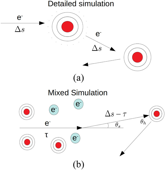
MC simulations are accurate ways to solve the problem of particle transport in matter. In the literature, two possible approaches are suggested: the detailed and the condensed algorithms.17,26 In the detailed method, all the collisions experienced by a particle are simulated. The particle history is composed of a succession of connected straight segments of free flight between each collision. Changes in direction are sampled from scattering cross sections that account for the physical properties of the scattering centers, and the simulated tracks can be considered as the real particle tracks. However, because of the high computational power required, detailed simulations are feasible only for a limited number of collisions, i.e., for low-energy electrons or for thin target geometries. Because of this limitation, condensed MC methods were formulated, allowing a reduction in computational time. Here, a particle moves through distances (steps) greater than its mean free path, and the effects of the scattering centers on the particle direction are computed according to a multiple-scattering theory. The accuracy of these algorithms depends on the approximation and on the hypothesis of the multiple-scattering theory that are used.
Another possibility suggested in the literature is the so-called mixed algorithm.16,17 In this approach, “soft” collisions are described according to multiple-scattering theories, while “hard” collisions are simulated individually, i.e., considering a two-body interaction. Here, we develop a mixed simulation algorithm aimed at simulating hot-electron transport in laser-irradiated targets, considering the regimes of interest for ICF. In particular, the algorithm presented follows closely the implementation of the Penelope MC code,17,20 although modifications are required because of the different nature of the problem. Penelope simulates the propagation of electrons in standard nonionized materials, whereas here we are considering laser-irradiated targets. Under these conditions, a hot electron propagates in an ionized medium, scattering with other free plasma electrons and with completely or partially ionized atoms. In particular, collisions with other electrons (free or bound) are accompanied by energy transfer, while collisions with nuclei are responsible for changes in direction (because of the difference in the masses of the interacting particles). In this work, the beam diffusion and the electron slowing down are treated separately. As reported in Sec. V, appropriate stopping power formulas are adopted to model the electron energy losses due to collisions with free and bound electrons. Energy losses due to excitation of plasma waves are also taken into account. Considering the typical uncertainties that characterize laser–plasma experiments, the continuous slowing down approximation (CSDA) is considered sufficiently accurate. The changes in direction of the hot electrons direction are simulated taking account of diffusion on plasma nuclei and on free electrons, according to appropriate DCSs (see Sec. III). Changes in direction due to collisions with bound electrons are not simulated. As shown in Paper II,25 beam diffusion is governed mainly by scattering on plasma nuclei, while scattering with other electrons plays a minor role. As a consequence, the fact that we do not simulate the changes in direction due to scattering with bound electrons does not introduce a significant error in the model.
A final important point is that a laser-irradiated target exhibits strong density gradients, which means that the algorithms used in cold MC methods to compute the collision distances are not adequate. For this purpose, we have developed an algorithm to calculate the collision distances in materials characterized by a nonconstant density.
In the code, we also implemented a “cold module.” When the material temperature goes to zero, electrons collide with nonionized atoms. Appropriate DCSs and stopping power formulas are implemented to describe this condition. This will make it easy for us to benchmark the code against cold MC codes like Geant4.
III. CROSS SECTIONS
In this section, we give a list of DCSs that model the scattering undergone by an electron propagating in a plasma. In particular, elastic scattering with atomic nuclei or with other free electrons and inelastic scattering with the electronic structure of an atom are the processes responsible for the modification of electron direction and energy loss. As mentioned in Sec. II, changes in electron direction are simulated taking account of collisions on plasma nuclei and free electrons, while collisions with bound electrons are neglected. The DCSs considered in our model are the Møller DCS to model collisions between a hot electron and a free plasma electron, the Dalitz DCS to model elastic collisions between a hot electron and a nucleus screened by plasma particles, and a DCS is proposed to model the elastic collision between the hot electron and a nucleus screened by its residual electronic structure and by other plasma particles. The Wentzel DCS is used to model the interaction between an electron and a nucleus screened by its complete electronic structure.
A. Electron–electron scattering
The scattering between a hot electron and plasma electrons can be modeled considering the Møller cross-section.27,28 This formula takes account the quantum nature of the interacting particles, but it neglects the motion of the target electron. In the center-of-mass reference frame, the cross section is written as
B. Electron–nucleus elastic scattering
In this subsection, we present the analytical forms of the DCS describing the elastic interaction between a hot electron and a nucleus. We consider, in particular, three different cases. The first is the collision between the electron and a nucleus that is screened by its complete electronic structure. We are thus considering a cold nonionized material. In the second case, we consider partial ionization, i.e., an elastic collision between the electron and a nucleus screened by its residual electronic structure and by other plasma particles. In the third case we present the DCS describing the collision between the electron and a nucleus screened by other plasma particles. We are thus considering atoms that are completely ionized.
1. Nonionized case
As mentioned in Sec. II, in the code, we take into account the possibility for the electron to propagate in “cold” materials, i.e., nonionized materials. Notably, this happens when T → 0 and the degree of ionization drops to zero. The ability to simulate the propagation of hot electrons in cold materials will make it easy to benchmark the code against existing and widely used MC codes like Geant4 and Penelope. The DCS describing the collision between an electron and a nucleus screened by its electronic structure is the Wentzel cross section:30
2. Partial ionization
In the ICF regime, the atoms of which the targets are composed can be characterized as being partial ionized. Thus, hot electrons scatter with nuclei that are screened by other plasma particles and by their residual electronic structure. This condition has been addressed in some unpublished theses,34–36 in which the authors have proposed an analytical form for the screening distance as a function of the ionization state of the element. Here, we adopt another approach, deriving an analytical DCS that describes this phenomenon.
To model the interaction between an electron and the nucleus of a partially ionized atom, we consider a potential V(r) of the form37
To better understand the model, we study the behavior of the potential (7) as a function of r:
In the case of a large scattering angle, the screening terms play a minor role. Since B ≪ 1 and F ≪ 1, in this case, the cross section (10) reduces to the Rutherford cross section:
3. Complete ionization
As already mentioned, in ICF and SI, the generation of hot electrons happens after the compression laser pulses. These pulses have duration and intensity sufficient to completely ionize part of the atoms in the capsule. Thus, hot electrons will interact with completely ionized atoms screened by plasma charges. This condition has been already considered in the literature, in particular to model the propagation of electrons in the fast ignition regime (i.e., electrons with energy of the order of MeV).29 A suitable DCS that describes the electron–nucleus interaction considering the screening effects is the Dalitz DCS:48–50
This DCS is derived according to the second Born approximation (Z/137β)2 ≪ 1 and it is valid in the relativistic regime.
IV. SCATTERING THEORIES: SCATTERING POLAR ANGLE DISTRIBUTION FOR SOFT AND HARD COLLISIONS
The algorithm proposed here follows closely the method used in the Penelope MC code,17,20 even if some modifications are required because of the different nature of the problem. As in Penelope, we have implemented a mixed algorithm in which soft and hard collisions are simulated separately. We identify as soft collisions those scattering events for which the polar scattering angle is less than a predetermined value θs, which is around 10°17 (the exact value of θs does not have a large impact on the final results of the simulation). Evidently, hard collisions are such events with a scattering angle greater than θs. Soft scattering events are modeled according to the Goudsmit and Saunderson theory,51–53 while hard collisions are simulated considering a two-body interaction according to the DCSs listed in Sec. III.
A. Multiple scattering theory
A multiple-scattering theory evaluates the global effect of the collisions that occur in a track segment of a given length traveled by the electron. An accurate simulation procedure is based on the Goudsmit–Saunderson multiple-scattering theory.51,52 The most important result obtained from this theory is the fact that in the soft scattering angle approximation, the soft collision polar angle can be sampled from the distribution FGS(θ, Δs), which does not differ significantly from the Gaussian distribution with variance :17
This analytical distribution provides a simple tool to generate the angular deflection caused by soft collisions experienced by the hot electrons.
B. Hard collisions
Hard collisions, i.e., collisions that cause the primary particle to deviate with a polar scattering angle greater than θs, are simulated considering a two-body interaction. In particular, the primary electron can scatter with other free plasma electrons or nuclei. The probability distribution for the polar scattering angle reads17,20
V. STOPPING POWER
In recent decades, with the increasing interest in nuclear fusion, particular attention has been devoted to study of the energy loss of electrons in plasmas.54–57 As already mentioned in the preceding sections, a hot electron that propagates in a plasma undergoes several collisions with other electrons (free or bound) or with nuclei. Collisions with free plasma electrons or with the remaining electronic structure of an atom are accompanied by energy transfer. Collisions with nuclei cause mostly changes in electron direction, while the energy transfer is limited because of the greater mass of the nucleus. Another source of energy loss is the excitation of plasma waves. In this case, the electric field generated by a hot electron makes the plasma electrons oscillate, leading to energy transfer between the hot electron and the medium.
In this section, we describe the different sources of energy loss for a hot electron propagating in a plasma, together with the equations governing the process.
A. Energy loss in electron–electron collisions
While propagating in a plasma, a hot electron collides with other free plasma electrons. Since the two colliding particles have the same mass, the primary particle may transfer part of its energy to the plasma electron. This phenomenon is treated in Ref. 54 and the linear energy loss due to binary electron–electron collisions is given by the following formula:
B. Energy loss in electron–atom inelastic collisions
An energetic electron that propagates in a medium experiences collisions with atoms. In particular, the electron may undergo an inelastic collision and transfer energy to the electronic structure of an atom. As remarked in Sec. II, these collisions do not influence strongly the direction of the primary particle, but, conversely, they play an important role in the electron energy loss. This energy transfer is modeled considering the mean excitation potential I. In the case of an ionized medium, this can be computed as a function of the degree of ionization of the atom:40,59
To calculate the electron stopping power, I is used in the Bethe–Bloch formula:64
In the case of mixed species, it is assumed that the stopping power additivity rule is a good approximation. For a medium containing N species, this rule reads
C. Energy loss due to plasmon excitation
The formulas given in Secs. V A and V B describe the electron energy loss due to binary collisions with other free plasma electrons or with partially ionized atoms (or with nonionized atoms in the cold case). These interactions are relevant, and the corresponding formulas are correct, if the electron passes at distances from the target particle less than the Debye length (or ion sphere radius). For greater interaction distances, the plasma acts as a continuous medium in which the charged particles participate in collective behavior, responding to the electric field generated by the hot electron.65 In particular, the hot electron loses energy by exciting plasma oscillations. A nonrelativistic treatment of the phenomenon is given in Ref. 43, and the stopping power formula that describes the loss of energy due to plasma wave excitation is
D. Bremsstrahlung emission and Fermi effect
We have not so far mentioned the energy losses due to bremsstrahlung generation. This effect is important for electron kinetic energies greater than ∼MeV, and so it can be neglected in our regime. In particular, the ratio between the collisional and bremsstrahlung energy losses in cold material is66
Let us also mention that in the cold case, the Fermi density effect is neglected. This effect reduces the value of the stopping power because of the atom polarization in the medium43 and it becomes important for highly energetic electrons (∼MeV).
VI. PROPAGATION ALGORITHM
As mentioned in Sec. I, a mixed simulation algorithm was chosen to simulate the hot electron propagation. In particular, the beam diffusion is modeled considering soft and hard collisions with nuclei and free plasma electrons, while the electron slowing down is simulated using the formulas presented in Sec. V. The algorithm is implemented following closely the method used in the Penelope MC code,17,20 although with some modifications that are required because of the different nature of the problem. Notably, in addition to the modifications to the stopping powers and scattering cross sections, our numerical method differs from Penelope in the following ways:
The steps of the algorithm are as follows:
If λ > Csλ1, then the simulation is detailed and the scattering phenomena are simulated individually (i.e., a two-body interaction is simulated). Conversely, if λ < Csλ1, the simulation enters the mixed mode, and soft and hard scattering phenomena are simulated separately. In our case, the simulation runs for the most of the time in mixed mode. Only when the electron has energy around ∼10–20 keV does the detailed algorithm come into play, but, at this point, the particle will experience only a few collisions before being completely stopped. The two algorithms proceed as follows.
A. Detailed simulation
B. Mixed simulation
![]()
Figure 1.Schematic representation of the two algorithms: (a) detailed simulation algorithm; (b) mixed simulation algorithm. In a detailed simulation, each scattering event is simulated individually in a two-body interaction. In the mixed algorithm, soft and hard collisions are simulated separately.
![]()
Figure 2.Grid element of the mesh in which the electron propagates. The position of each node is indicated by the vector
Let us mention that according to this algorithm, the history of each electron is followed individually, and the electrons scatter and lose energy according to the physical phenomena described in the preceding sections. It is well known, however, that the propagation of electrons emitted by laser–plasma interaction can be affected by the presence of collective effects and self-consistent electric and magnetic fields. These effects were neglected in previous studies of hot-electron transport in the fast ignition (FI) context.29,70,71 Furthermore, in Ref. 72, the authors evaluated the importance of the collective losses on the propagation of hot electrons in the context of SI, asserting that these are negligible because of the low intensities of the electron beam. The evaluation of the collective effects and the impact of the self-generated electromagnetic fields on hot-electron propagation is an open topic, and it can provide motivation for future work.
Another aspect that is not simulated by our model is the generation of secondary electrons. These electrons are generated by the hard collision of the primary particle with plasma or bound electrons, which become suprathermal. As noted in Paper II,25 hard collisions should not be neglected, since they strongly modify the directions of the hot electrons. While the simulation of secondary electrons is important in fields in which a high degree of precision is required (e.g., radiotherapy), given the typical uncertainties in laser–plasma experiments, their absence should not cause any great problems. However, the need to understand and evaluate the effect of secondary electrons again provides motivation for future investigations.
It is worth mentioning that it is important to be aware of numerical errors in the code, which need to be minimized. In particular, the absolute number of particles launched in the simulation should be sufficiently high to minimize the statistical fluctuations of the physical quantities considered. Another source of numerical error is related to the grid element dimension. In fact, large tetrahedron dimensions will cause erroneous computation of the electron stopping power. It is therefore necessary to set a sufficiently fine mesh and a sufficiently high number of particles to obtain accurate results, even if this causes a degradation in the performance of the simulation.
C. Calculation of mean free path in an inhomogeneous medium
This subsection describes an algorithm suitable for calculating the collision distance Δs of an electron propagating inside an inhomogeneous medium. In cold MC methods, the collision distance is sampled from an exponential distribution at the beginning of the electron history [see Eq. (30)]. However, this procedure is not adequate for our purposes. In fact, in the case of laser-irradiated targets in the ICF context, the material density can vary by orders of magnitude in several tens or hundreds of micrometers. As an example, Fig. 3 shows the density profile of a planar CH target irradiated with a laser of intensity 1016 W/cm2, after 500 ps of irradiation. The density goes from 0.05 g/cm3 at x = 0 (coronal plasma) to 4 g/cm3 (shocked region) after 30 µm. An electron initialized at x = 0 will be characterized by a large mean free path λ(E, ρ), since the material density is very low. Because of this, the electron propagates for the first 20–30 µm without experiencing any collisions, but at this point the material density is much higher. The value of λ(E, ρ) computed at the beginning of the electron history is no longer valid in this new condition.
![]()
Figure 3.Density profile of a CH planar target irradiated by a laser at an intensity of 1016 W/cm2. The density profile is extracted from a hydrodynamic simulation using the CHIC
An approximate method to compute the collision distance in a nonhomogeneous medium is presented in Ref. 74. This method was originally developed for neutral particles, but it is adequate for our purposes. Let us consider a neutral particle that propagates in a heterogeneous medium. In our case, this medium is composed of small volumes, the grid elements, within each of which the material is homogeneous (see Fig. 4). The collision distance should be recomputed at each cell interface, taking into account the path already traveled and the density variations. If the particle crosses cells 1 and 2, traveling distances l1 and l2, the collision distance in cell 3 can be sampled according to the following formula:
![]()
Figure 4.Calculation of the collision distance for an electron moving in a computational domain subdivided into triangular cells. In each cell
If Δs3 < l3, the particle is transported by x = l2 + Δs3 and the collision is simulated. Conversely, if Δs3 > l3, the particle is propagated up to the boundary of cell 3 and Δs4 is computed by adding the term to the right-hand side of Eq. (40) and replacing by .
From a practical point of view, the collision distance Δs is calculated by launching a “fictitious” particle before the real electron track. These fictitious particles have the same kinetic energy as the electron and they propagate following straight lines in the grid, as shown in Fig. 4. Referring to the figure, the particle starts in tetrahedron 1, where the collision path is computed according to Eq. (30):
VII. BENCHMARK AGAINST GEANT4
In this section, we describe a benchmark of our 3D MC code against Geant4 used with the library Penelope. This was done by performing simulations in which the same target geometry and electron beam characteristics were adopted and then comparing the results from the two codes. In these simulations, we made use of the “cold model,” i.e., we considered electrons propagating in nonionized materials. We recall that under these conditions, atoms are not ionized and electrons scatter with nuclei screened by their complete electronic structure. In this case, the scattering cross sections were modeled according to the Wentzel model (3), and the NIST stopping power formulas were used to compute the slowing down. It should be noted here that Geant4 implements more complex models to simulate the diffusion and the slowing down of the beam. Moreover, it simulates the emission of secondary electrons, an aspect completely neglected in our model. Nevertheless, a comparison between the two codes is useful to estimate the margin of error introduced by our model and its reliability.
A first benchmark was conducted by comparing the energy deposition of electrons in matter. This quantity plays a primary role in the calculation of shell preheating in the SI scheme, and it is therefore necessary to assess the reliability of our numerical method. For this purpose, monochromatic electron beams were injected in a 200 µm thick 0.4 × 0.4 mm2 slab and the total energy deposit was computed. Electrons were initialized considering a 100 µm diameter spot with an initial beam divergence of 22°. The initial beam energy ranged from 20 to 800 keV, and each run consisted of 10 000 particles. To evaluate the reliability of the model for different atomic numbers, several materials were considered: beryllium, aluminum, titanium, copper, tungsten, and gold. We also considered CH, since this material is relevant to ICF. As an example, the results for the cases beryllium and gold are shown in Fig. 5.
![]()
Figure 5.Energy deposition in a 0.4 × 0.4 mm2, 200
Overall, for low-Z materials (Be and Al), our model reproduces the Geant4 energy deposition with an error that is smaller than 10%. In the cases of Ti and Cu, the discrepancy between the two codes remains below 20%, while for the highest values of Z (W and Au), the error does not exceed 50%. The agreement between the two codes is particularly good for electron energies in the range 40–180 keV, especially for low-Z materials, where the error is around 1%. The discrepancies between the two codes at lower energies, especially for high-Z materials, may be due to the fact that in this regime, the first Born approximation no longer holds, and therefore the stopping power formulas and the Wentzel DCS used in our model are not accurate. Moreover, for higher electron energies (≥600 keV), the disagreement between the codes may be due to the fact that our code does not take account of the bremsstrahlung energy losses, the Fermi density effect, and the secondary electron emission. These discrepancies, however, should not represent a significant issue. First of all, in direct-drive ICF, hot electrons propagate in low-Z materials (the plastic ablator and DT cryogenic shell). Furthermore, low-energy electrons (∼10–20 keV) will be suddenly stopped in the compressed shell and do not represent a preheating concern. Conversely, electrons with energy greater than 40 keV can penetrate deeper in the cryogenic shell, preheating the fuel. The fact that our model reproduces the Geant4 results in this energy range with an error around 1% is an important achievement that gives us more confidence in the reliability of the code.
Special attention was devoted to the benchmark of the code for CH, because of its relevance to ICF. Figure 6 represents the energy deposited by monochromatic electron beams in a 0.4 × 0.4 mm2, 200 µm thick CH slab, comparing our model with Geant4. As can be seen, our code reproduces the Geant4 results with an error that is smaller than 5%, establishing the accuracy of the additivity rule in the calculation of the stopping power (27). Furthermore, Fig. 6 shows the energy deposition in the case of CH characterized by a small degree of ionization (black crosses). In particular, we set the material temperature at 1 eV, a condition under which each carbon atom releases one electron (on average). It can be seen that the values of energy deposition in the ionized case are slightly greater than in the cold case. This happens, in particular, for the energy range 160–250 keV, in which the discrepancy with the cold case is around 7%–8%. In particular, electrons with energy grater than 150 keV reach the rear side of the target and escape, whereas in the plasma case, they are more strongly absorbed. This will be carefully demonstrated in Paper II.25 However, it can be seen from Fig. 6 that for a small degree of ionization, the code converges to the cold limit. A second benchmark was conducted comparing the electron transport in CH targets. We considered in particular 0.4 × 0.4 mm2 plastic slabs with two different thicknesses: 200 and 275 µm. Electrons were launched inside the target, with a 2D Maxwellian distribution function with temperature 26 keV. This value was chosen on the basis of recent experimental findings on hot-electron characterization in the context of SI.24
![]()
Figure 6.Energy deposition in a 0.4 × 0.4 mm2, 200
The particles were initialized in a 100 µm diameter spot with an initial beam divergence of ±22°. Electrons were launched at a distance of 100 µm from the left side of the target, as shown in Fig. 7(a). As a figure of merit for the benchmark, we compared the electron energy spectra at the exit from the target. As can be seen from Figs. 7(b) and 7(c), there is a good agreement between the two codes in the prediction of the electron spectrum at the exit from the target. This is a further important validation of our model with regard to its reliability for the energy range considered. Other benchmarks are proposed in Paper II,25 in which a more realistic scenario based on recent experimental results is considered, as well a the limit of small density gradients, to evaluate the reliability of the algorithm presented in Sec. VI A.
![]()
Figure 7.(a) Schematic representation of simulations performed to benchmark our MC model against Geant4. Electrons were injected into a 0.4 × 0.4 mm2 CH slab at 100
VIII. CONCLUSION
This paper has described the physical basis and the implementation of a 3D Monte-Carlo code to model hot-electron propagation in fusion targets, with the aim of future implementation in hydrodynamic codes. In contrast to the usual MC methods (e.g., Geant4), this model simulates hot-electron propagation in ionized or partially ionized targets, taking into account the presence of the plasma state. Under these conditions, electrons scatter with other electrons (free or bound) and with nuclei screened by their residual electronic structure and by other plasma particles. The energy losses occur in collisions with other electrons, while collisions with plasma nuclei govern the beam diffusion. These phenomena are modeled using appropriate DCSs and stopping power formulas. In particular, an analytical DCS is proposed to model the elastic scattering between a hot electron and a nucleus screened by its residual electronic structure and by other plasma charges.
The MC method is developed following the so-called mixed algorithm approach. Here, electrons propagate for distances greater than their mean free paths, and the new directions are evaluated according to multiple-scattering theories. In particular, soft collisions are modeled according to Goudsmit–Saunderson theory, while hard collisions are simulated on the basis of a two-body interaction. The electron slowing down and the energy deposition are computed in the continuous slowing down approximation. An important difference with the cold MC methods is that electrons propagate in targets in which strong density gradients are present, and, notably, ablation and compression waves are generated by the laser interaction. Given these considerations, a new algorithm to evaluate the electron collision distance in inhomogeneous materials is developed.
The propagation of electrons in cold materials (i.e., nonionized materials under standard conditions) can also be simulated thanks to a cold module that uses appropriate stopping power formulas and cross sections. This module is used to benchmark the algorithm against Geant4, considering different figures of merit in the comparison. Overall, our model exhibits very good agreement with Geant4 in the description of hot-electron transport and energy deposition in targets.
Compared with previous plasma MC methods,29 the MC code presented here enables simulation of the propagation of hot electrons in partially ionized materials. This is particularly useful in the analysis of laser–plasma experiments in which the interaction conditions do not allow complete target ionization to be achieved. Furthermore, an important improvement is the simulation of hard collisions.
In Paper II,25 we report two numerical investigations performed using the plasma MC developed here, studying how the presence of plasma affects hot-electron propagation and performing an initial analysis of the hot-electron-induced preheating in a typical implosion scheme. In particular, a detailed study is conducted with the aim of determining the main features that influence hot-electron propagation in ionized targets (i.e., laser-irradiated targets) and comparing the results with those in the cold case (i.e., nonionized materials under standard conditions). Overall, targets in the plasma state are more effective than cold targets in stopping and absorbing hot electrons. This is due in part to the fact that the plasma stopping power is greater than the cold stopping power, and in part to enhanced beam diffusion on plasma nuclei. In fact, in this regime, the screening distances in a plasma (the parameter D in Sec. III) are greater than those in cold materials (the parameter R in Sec. III), and the range of nuclear potentials is greater in a plasma. It is also shown in Paper II that the dominant contribution to beam diffusion comes from the nuclei rather than the free plasma electrons, justifying our decision to neglect the changes in direction due to collisions with bound electrons. Furthermore, in Paper II, some simulations are conducted to understand the importance of hard collisions, which should not be neglected.
Further investigations will be required to understand the importance of collective effects and the generation of secondary electrons. However, the code is ready for implementation in hydrodynamic codes, providing a basis for the development of robust SI implosion schemes. Finally, if bremsstrahlung and Kα generation can be added, it will then be possible to interpret laser–plasma experiments without relying on cold MC methods. Further benchmarks and information on the code can be found in Ref. 75.
ACKNOWLEDGMENTS
Acknowledgment. This work has been carried out within the framework of the EUROfusion Enabling Research Project No. AWP17-ENR-IFE-CEA-01 “Preparation and Realization of European Shock Ignition Experiments” and has received funding from the Euratom Research and Training Program 2014–2018 under Grant Agreement No. 633053. The views and opinions expressed herein do not necessarily reflect those of the European Commission. The authors thank Professors Vladimir Tikhonchuk and Stefano Atzeni for many useful discussions. We also thank the anonymous reviewers for their constructive comments.
References
[1] J.Nuckolls, L.Wood, G.Zimmerman, A.Thiessen. Laser compression of matter to super high densities: Thermonuclear (CTR) applications. Nature, 239, 139-142(1972).
[2] H. D.Hora, O. N.Krokhin, N. G.Basov, H. J.Schwarz, G. V.Sklizkov. Heating of laser plasmas for thermonuclear fusion. Laser Interaction and Related Plasma Phenomena, 2, 389.22(1972).
[3] V. A.Shcherbakov. Ignition of a laser fusion target by a focusing shock wave. Sov. J. Plasma Phys., 9, 240(1983).
[4] W.Theobald, R.Betti, A. A.Solodov, K. S.Anderson, L. J.Perkins, C. D.Zhou. Shock ignition of thermonuclear fuel with high areal density. Phys. Rev. Lett., 98, 155001(2007).
[5] B.Canaud, L. J.Perkins, R.Betti, S.Atzeni, A. J.Schmitt, G.Schurtz, X.Ribeyre. Shock ignition of thermonuclear fuel: Principles and modelling. Nucl. Fusion, 54, 054008(2014).
[6] T. C.Sangster, V. N.Goncharov, R. L.McCrory, P. B.Radha, J. P.Knauer, D. D.Meyerhofer, S.Skupsky, R.Betti, P. W.McKenty. Improved performance of direct drive inertial confinement fusion target designs with adiabat shaping using an intensity picket. Phys. Plasmas, 10, 1906-1918(2003).
[7] W. L.Kruer. The Physics of Laser Plasma Interactions(2003).
[8] B. B.Afeyan, E. A.Williams. Stimulated Raman sidescattering with the effects of oblique incidence. Phys. Fluids, 28, 3397-3408(1985).
[9] M. N.Rosenbluth, C. S.Liu. Parametric decay of electromagnetic waves into two plasmons and its consequences. Phys. Fluids, 19, 967-971(1976).
[10] V.Tikhonchuk, G.Duchateau, E.Le Bel, A.Cola?tis, P.Nicola?, X.Ribeyre. Influence of laser induced hot electrons on the threshold for shock ignition of fusion reactions. Phys. Plasmas, 23, 072703(2016).
[11] N. V.Zmitrenko, S. Y.Guskov, P. A.Kuchugov, R. A.Yakhin. Effect of fast electrons on the gain of a direct-drive laser fusion target. Plasma Phys. Controlled Fusion, 61, 105014(2019).
[12] N.Zmitrenko, S.Guskov, P.Kuchugov, R.Yakhin. The role of fast electron energy transfer in the problem of shock ignition of laser thermonuclear target. High Energy Density Phys., 36, 100835(2020).
[13] D. D.Meyerhofer, C.Stoeckl, J. A.Frenje, V. N.Goncharov, P. B.Radha, S. P.Regan, R.Betti, R. D.Petrasso, R. L.McCrory, F. H.Séguin, D. H.Edgell, D.Shvarts, B.Yaakobi, W.Seka, C. K.Li, T. C.Sangster, S.Skupsky, V. Y.Glebov, J. A.Delettrez, V. A.Smalyuk. Role of hot-electron preheating in the compression of direct-drive imploding targets with cryogenic D2 ablators. Phys. Rev. Lett., 100, 185005(2008).
[14] K. S.Anderson, A. A.Solodov, R.Betti, J. A.Delettrez, J. A.Frenje, X.Ribeyre, C.Stoeckl, M.Stoeckl, D.Batani, V. Y.Glebov, J.Trela, A.Casner, W.Theobald. The control of hot-electron preheat in shock-ignition implosions. Phys. Plasmas, 25, 052707(2018).
[15] P.Andreo, A.Brahme. Restricted energy-loss straggling and multiple scattering of electrons in mixed Monte Carlo procedures. Radiat. Res., 100, 16-29(1984).
[16] L.Reimer, D. N. H.Yakowitz, E. R.Krefting, K.Heinrich. The effect of scattering models on the results of Monte Carlo calculations. Use of Monte Carlo Calculations in Electron Probe Microanalysis and Scanning Electron Microscopy, 45-60(1976).
[17] J.Baró, J. M.Fernández-Varea, F.Salvat, R.Mayol. On the theory and simulation of multiple elastic scattering of electrons. Nucl. Instrum. Methods Phys. Res., Sect. B, 73, 447-473(1993).
[18] D.Axen, S.Agostinelli, S.Banerjee, K.Amako, J.Apostolakis, H.Araujo, M.Asai, J.Allison, P.Arceet?al.. Geant4—A simulation toolkit. Nucl. Instrum. Methods Phys. Res., Sect. A, 506, 250-303(2003).
[19] X.Llovet, R.Chawla, C.Negreanu, F.Salvat. Calculation of multiple-scattering angular distributions of electrons and positrons. Radiat. Phys. Chem., 74, 264-281(2005).
[20] F.Salvat. PENELOPE: A Code System for Monte Carlo Simulation of Electron and Photon Transport(2019).
[21] L.Antonelli, M.?míd, D.Batani, O.Renner. Suprathermal electron production in laser-irradiated Cu targets characterized by combined methods of x-ray imaging and spectroscopy. Plasma Phys. Controlled Fusion, 58, 075007(2016).
[22] J.Feugeas, G.Boutoux, D.Mancelli, V.Tikhonchuk, L.Antonelli, G.Folpini, D.Batani, J.Santos, A.Colaitis, F.Barbatoet?al.. Progress in understanding the role of hot electrons for the shock ignition approach to inertial confinement fusion. Nucl. Fusion, 59, 032012(2018).
[23] F.Barbato, L.Antonelli, P.Nicola?, D.Mancelli, V.Tikhonchuk, S.Atzeni, A.Tentori, D.Batani, J.Trela, G.Boutoux. Laser-driven strong shocks with infrared lasers at intensity of 1016 W/cm2. Phys. Plasmas, 26, 112708(2019).
[24] M.Wei, A.Colaitis, A.Tentori, A.Casner, W.Theobald, D.Raffestin, A.Ruocco, E.Le Bel, K.Anderson, J.Trelaet?al.. Experimental characterization of hot-electron emission and shock dynamics in the context of the shock ignition approach to inertial confinement fusion. Phys. Plasmas, 28, 103302(2021).
[25] A.Cola?tis, D.Batani, A.Tentori. 3D Monte-Carlo model to study the transport of hot electrons in the context of inertial confinement fusion: Part II. Matter Radiat. Extremes, 7, 065903(2022).
[26] M. J.Berger. Monte Carlo calculation of the penetration and diffusion of fast charged particles. Methods in Computational Physics, Volume 1, 135-215(1963).
[27] C.Moller. Zur theorie des durchgangs schneller elektronen durch materie. Ann. Phys., 406, 531-585(1932).
[28] L. D.Landau, L. P.Pitaevskii, E. M.Lifshitz, V. B.Berestetskii. Relativistic Quantum Theory(1971).
[29] A.Schiavi, S.Atzeni, J. R.Davies. Stopping and scattering of relativistic electron beams in dense plasmas and requirements for fast ignition. Plasma Phys. Controlled Fusion, 51, 015016(2008).
[30] G.Wentzel. Zwei bemerkungen über die zerstreuung korpuskularer strahlen als beugungserscheinung. Z. Phys., 40, 590-593(1926).
[31]
[32] J. C.Stewart, M.Rotenberg. Wave functions and transition probabilities in scaled Thomas-Fermi ion potentials. Phys. Rev., 140, A1508-A1519(1965).
[33] A. S.Davydov. Quantum Mechanics(1965).
[34] L. Y. A.Gremillet. Etude theorique et experimentale du transport des electrons rapides dans l’interaction laser-solide à tres haut flux(2001).
[35] B.Martinez. Effets radiatifs et quantiques dans l’interaction laser-matiere ultra-relativiste(2018).
[36] X.Vaisseau. Experimental study of fast electron transport in dense plasmas(2014).
[37] E.Nardi, Z.Zinamon. Energy deposition by relativistic electrons in high-temperature targets. Phys. Rev. A, 18, 1246-1249(1978).
[38] S. G.Brush, H. L.Sahlin, E.Teller. Monte Carlo study of a one-component plasma. I. J. Chem. Phys., 45, 2102-2118(1966).
[39] Y. T.Lee, R. M.More. An electron conductivity model for dense plasmas. Phys. Fluids, 27, 1273-1286(1984).
[40] R. M.More. Processes in non ideal plasmas, 135-215(1986).
[41] D.Salzmann. Atomic Physics in Hot Plasmas(1998).
[42] R. P.Drake. High-Energy-Density Physics(2018).
[43] J. D.Jackson. Classical Electrodynamics(1975).
[44] S. P.Regan, P.Michel, W.Seka, J. F.Myatt, M. J.Rosenberg, R. W.Short, E. M.Campbell, R.Epstein, M.Hohenberger, A. A.Solodovet?al.. Origins and scaling of hot-electron preheat in ignition-scale direct-drive inertial confinement fusion experiments. Phys. Rev. Lett., 120, 055001(2018).
[45] M. J.Rosenberg, S. P.Regan, R.Epstein, P.Michel, W.Seka, M.Hohenberger, R. W.Short, J. F.Myatt, A. A.Solodov, C.Stoecklet?al.. Hot-electron generation at direct-drive ignition-relevant plasma conditions at the National Ignition Facility. Phys. Plasmas, 27, 052706(2020).
[46] D.Batani, A.Casner, S.Brygoo, M.Koenig, S. D.Baton, L.Jacquet, A.Cola?tis, G.Boutoux, E. L.Bel, C.Rousseauxet?al.. Preliminary results from the LMJ-PETAL experiment on hot electrons characterization in the context of shock ignition. High Energy Density Phys., 36, 100796(2020).
[47] S.Baton, A.Cola?tis, F.Baffigi, M.Koenig, A.Casner, L.Labate, D.Batani, P.Koester, G.Cristoforetti, L. A.Gizziet?al.. Bremsstrahlung cannon design for shock ignition relevant regime. Rev. Sci. Instrum., 92, 013501(2021).
[48] R. E.Peierls, R. H.Dalitz. On higher born approximations in potential scattering. Proc. R. Soc. London, Ser. A, 206, 509-520(1951).
[49] T.-Y.Wu, B. P.Nigam, M. K.Sundaresan. Theory of multiple scattering: Second born approximation and corrections to Molière’s work. Phys. Rev., 115, 491-502(1959).
[50] H.Olsen, H. W.Koch, J. W.Motz. Electron scattering without atomic or nuclear excitation. Rev. Mod. Phys., 36, 881-928(1964).
[51] J. L.Saunderson, S.Goudsmit. Multiple scattering of electrons. Phys. Rev., 57, 24-29(1940).
[52] S.Goudsmit, J. L.Saunderson. Multiple scattering of electrons. II. Phys. Rev., 58, 36-42(1940).
[53] H. W.Lewis. Multiple scattering in an infinite medium. Phys. Rev., 78, 526-529(1950).
[54] R.Betti, A. A.Solodov. Stopping power and range of energetic electrons in dense plasmas of fast-ignition fusion targets. Phys. Plasmas, 15, 042707(2008).
[55] Y. A.Valchuk, N. B.Volkov. Energy losses of fast electrons in a beam plasma. Fiz. Plazmy, 21, 167-172(1995).
[56] M.Murakami, H.Furukawa, K.Nishihara, C.Deutsch, K.Mima. Interaction physics of the fast ignitor concept. Phys. Rev., 77, 2483(1996).
[57] T.Iwawaki, H.Habara, T.Yabuuchi, A.Okabayashi, K. A.Tanaka. Stopping and transport of fast electrons in superdense matter. Phys. Plasmas, 20, 083301(2013).
[58] L. P.Pitaevskii, E. M.Lifshitz, L. D.Landau. Physical Kinetics(1981).
[59] A. P. L.Robinson, J. R.Davies, T.Johzaki, J. J.Honrubia, D. J.Strozzi, R. J.Kingham, L.Gremillet, A. A.Solodov, M.Sherlock. Theory of fast electron transport for fast ignition. Nucl. Fusion, 54, 054003(2014).
[60] E. J.McGuire. Born-approximation electron ionization cross sections for Al
[61] Y. T.Lee, J. A.Harte. Suprathermal electron energy loss in partially ionized matter, 175-177(1983).
[62] H.Bichsel, J. A.Dennis, S. M.Seltzer, M. J.Berger, H. H.Anderson, M.Inokuti, D.Powers, J. E.Turner(2016).
[64] M. S.Livingston, H. A.Bethe. Nuclear physics C. Nuclear dynamics, experimental. Rev. Mod. Phys., 9, 245-390(1937).
[65] D.Bohm, D.Pines. A collective description of electron interactions: II. Collective vs individual particle aspects of the interactions. Phys. Rev., 85, 338-353(1952).
[66] G. F.Knoll. Radiation Detection and Measurement(1989).
[67] J.Sempau, J.Baró, F.Salvat, J. M.Fernández-Varea. Simplified Monte Carlo simulation of elastic electron scattering in limited media. Nucl. Instrum. Methods Phys. Res., Sect. B, 84, 465-483(1994).
[68] V.Giménez-Alventosa, M. A.Cortés-Giraldo, V.Giménez Gómez, F.Salvat, M.Asai. The PENELOPE physics models and transport mechanics. Implementation into Geant4. Front. Phys., 9, 738735(2021).
[69] A.Cola?tis, J. P.Palastro, R. K.Follett, V.Goncharov, I. V.Igumenschev. Real and complex valued geometrical optics inverse ray-tracing for inline field calculations. Phys. Plasmas, 26, 032301(2019).
[70] J. J.Honrubia, J.Meyer-ter-Vehn. Three-dimensional fast electron transport for ignition-scale inertial fusion capsules. Nucl. Fusion, 46, L25-L28(2006).
[71] J. J.Honrubia, J.Meyer-ter-Vehn. Ignition of pre-compressed fusion targets by fast electrons. J. Phys.: Conf. Ser., 112, 022055(2008).
[72] J.-L.Feugeas, X.Ribeyre, V. T.Tikhonchuk, S.Gus’kov, P.Nicola?. Dense plasma heating and Gbar shock formation by a high intensity flux of energetic electrons. Phys. Plasmas, 20, 062705(2013).
[73] P.-H.Maire, S.Galera, J.Breil. Multi-material ALE computation in inertial confinement fusion code CHIC. Comput. Fluids, 46, 161(2011).
[74] O. N.Vassiliev. Monte Carlo Methods for Radiation Transport(2017).
[75] A.Tentori(2022).

Set citation alerts for the article
Please enter your email address
© Copyright 2018-2021 | Chinese Laser Press. All Rights Reserved 沪ICP备15018463号-20