
Dongyi Shen, Guolin Zhao, Xianfeng Chen, Wenjie Wan, "Smith–Purcell radiation-like photoacoustic phased array," Chin. Opt. Lett. 21, 041901 (2023)
- Chinese Optics Letters
- Vol. 21, Issue 4, 041901 (2023)
Abstract
1. Introduction
Smith–Purcell radiation (SPR), a classical type of electromagnetic radiation generated from free electrons moving over a metallic grating[1], allows broadband emission of electromagnetic (EM) waves ranging from terahertz waves, visible light to X-ray[2–4], building up the foundation for the free-electron laser[5,6], which is capable of producing high-intensity coherent and broadband sources as electron microbunches travel through designed magnetic undulators in a similar manner[7]. Compared with other relativistic radiation sources such as synchrotron and cyclotron radiation[8,9], SPR-based free-electron light sources are more compact and tunable, given the fact that the wavelength of the emitted light depends on the energy of the electron beam as well as the structure of the periodic surroundings. This offers an opportunity to further shrink the size of these devices with the help of the recent development of nanofabrication technologies, making it even possible to realize on-chip implements of such SPR-based light sources[10–13].
When electron wave packages travel near a metallic grating, SPR is generated and belongs to a thresholdless process, behaving like a simple Bragg scattering of the evanescent waves carried along with the electrons, where a constant light velocity fundamentally defines the angle relations of radiation’s wavelength[14–17]. The speed of light directly determines the relative phase of scattering waves between two adjacent grating scatters. In a similar manner, a phased array, the emitters/scatters of a phase-controlled array, in microwaves[18,19], acoustics[20–22], and optics[23,24] can alter the emission angles by adjusting the relative phases in the array. The phase control can be easily implemented in the phased array case at each active emitter, while in the SPR case, the relative phases between two adjacent scatters are purely determined by the speed of light. It is interesting to explore analogous forms of SPR in other physical systems[25,26] like acoustics[27], phononics[28,29] and exciton-polariton[30], where the required excitation speed is more feasible compared to the photonic case. For example, a sharp shock wavefront can be analogously treated as an ultrabroadband acoustic wave source, imitating the moving free electron in the case of SPR.
In this work, we experimentally demonstrate a photoacoustic phased array with sequential laser-induced shock waves. The formed periodical grating results in a tunable acoustic radiation in the far field, where the radiation pattern exhibits an angular dispersion relation exactly like the SPR in the photonic case. Similar to its photonic counterpart, the observed photoacoustic phased array also depends on the effective moving velocity of excitation. These results connect the acoustic phased array to the concept of the Smith–Purcell effect, paving a new way for their practical application in microstructure sensing and coherent acoustic wave sources.
Sign up for Chinese Optics Letters TOC. Get the latest issue of Chinese Optics Letters delivered right to you!Sign up now
2. Methods
A classical SPR in photonics arises from the Bragg-type scattering of an electron wave package that is uniformly moving near a metal periodic grating. The electron can be considered as a single point source in time composed of ultrabroadband electromagnetic (EM) waves, which can be scattered into free space by each tooth on the grating. The scattered EM waves at a particular angle in the far field can be defined in their frequency/wavelength by the Bragg condition[15,17], where both the velocity of the moving electrons and the periodicity of the grating play a prominent role in the angular emission spectrum. Ideally, a sharp acoustic wavefront, e.g., shock wave, travels uniformly at a speed of
![]()
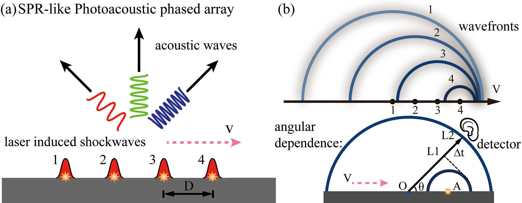
Figure 1.Schematic of SPR-like photoacoustic phased array in a degraded form. (a) SPR-like photoacoustic phased array in a degraded form; the sequentially (1→4) excited laser-shock array emits acoustic radiation into the far field. (b) Upper, the resultant multiple propagating wavefronts from the procedure in (a); integers 1→4 denote each source and every wavefront in time sequence (indicated by the color). Lower, the effective quasi-phase line (dashed, normal to OL1 and OL2) depicts the angle dependence in the broadband SPR-like pattern in (b). By the moment when the detector captures the first shock front (blue) from source O, the secondary shock front from source A propagates to the detector. The delay time (Δt) for the detector to catch the later shock wave varies with the detection angle; accordingly, the received frequency is also changed.
Due to the coherent constructions of wavefronts according to Huygens’ principle shown in Fig. 1(b), such an SPR-like photoacoustic phased array emits its frequency-dependent radiation in different angles, like its counterpart in the photonic case. Inspired by the photonic SPR, we can obtain a universal angular relation for the constant sound speed as
3. Experiments and Results
Figure 2 shows the experimental realization of the photoacoustic phased array. A nanosecond laser (
![]()
Figure 2.Experimental observation of SPR-like photoacoustic radiation from a linear phased array in the far field. (a) Given a rotating mirror with a stable angular speed ω, the pump is scanned and focused onto the target alumina plate sequentially in the order a0→a1→a2, forming an effective laser-induced plasma shock wave phased array. The detector is placed r = 0.1 m from the array center O. The detector acquires the SPR signals also in the order b0→b1→b2. For a fixed detection angle θ and rotating ω, the time delay Δt remains unchanged and irrelevant to the detector’s distance in the far field. (b) Snapshot of such an SPR-like linear phased array by laser-induced plasma; the periodicity D is about 6.57 mm. (c) Measured real-time temporal signal and (d) its corresponding spectrum with a peak frequency at 10.58 kHz. The signal is collected and processed at a surface scanning speed of 10 m/s (effective periodicity ∼1 mm) at θ = 0°.
Furthermore, by varying the detection angle
![]()
Figure 3.Angular and velocity dependence of the phased array emission in the far field. (a) and (b) testify to the velocity-dependent frequency with fixed detection angles 0° and 30°, respectively. Insets in (a) and (b) are the spectrum collected under the condition with surface velocity 65.7 m/s (effective grating period 6.57 mm) and 140.1 m/s (effective grating period 14.01 mm). (c) and (d) demonstrate the angular dependence in the photoacoustic SPR specially picked at surface velocities of 65.7 m/s and 140.1 m/s. The dots are experimental measurements, and the solid lines are the theoretical curves calculated by Eq. (
Following the original SPR formulism in the photonic case, Eq. (1) only indicates the ideal theoretical results of the dispersive angle relation for estimating the central frequency. However, given the limited number of scatters in the current acoustic case, to fully understand the radiation spectra as shown in Figs. 3(a) and 3(b), we have to incorporate the radiation theory[32] by considering the limited array length, source spacing, induced phase item, and limited detection range. A directivity function (
Figure 4 verifies the radiation spectra, as shown in the insets of Figs. 3(a) and 3(b) by comparing them with two theoretical calculations based on Eq. (2): one for the phased array in the far field (
![]()
Figure 4.Experimental (solid blue) and theoretical (black) radiation spectra at (a) θ = 0° and (b) θ = 30°; (a) N = 25 (number of acoustic sources on the target), vs = 65.7 m/s, θ = 0°; (b) N = 11, vs = 140.1 m/s, θ = 30°. The directly detected temporal signals are averaged 128 times before fast Fourier transform (FFT) processing into experimental data via an oscilloscope. Note that the dashed black curves (r = 0.1 m) are calculated by directly summing up all the phase-delayed acoustic sources and gathering radiated acoustic pressure amplitude at given conditions. The detection angle θ for r = 0.1 m calculation is defined from the center of the array.
4. Discussion and Conclusion
Similar to photonic SPR with an undulator configuration, our SPR-like photoacoustic phased array can also be tailored for particular acoustic wave emission in terms of bandwidth, frequency, and emission angle by engineering microstructured gratings, i.e., metamaterials. In this manner, a compact acoustic wave source with dispersive spreading frequency emission can be obtained, similar to an optical grating, which might be beneficial for some acoustic spectroscopy applications[33]. Meanwhile, acoustic SPR is not limited to free space; it is also applicable for bulk conditions, e.g., exciting phonons within layered materials[34]. For example, it has been proposed to generate terahertz waves using semiconductor superlattices by considering SPR-based phonon–photon interactions[35]. These photo-excited phonons have been well studied using ultrafast laser pulsed for their propagation and interaction[29,36]. We believe this acoustic analogy of the Smith–Purcell effect may finally open a new avenue in condensed matter, acoustics, and phononics.
In conclusion, we have demonstrated an SPR-like photoacoustic phased array based on laser-induced surface shock waves. The mechanisms of organizing such a related phase item in our photoacoustic case share a similarity to the original photonic SPR. As a result, the observed radiation spectrum in the far field can be well described by a universal theory working both for the photonic SPR and our acoustic one. We believe similar studies can be further extended to other physical systems like phonons in the solid-state system.
References
[1] S. J. Smith, E. M. Purcell. Visible light from localized surface charges moving across a grating. Phys. Rev., 92, 1069(1953).
[2] G. Doucas, J. H. Mulvey, M. Omori, J. Walsh, M. F. Kimmitt. First observation of Smith-Purcell radiation from relativistic electrons. Phys. Rev. Lett., 69, 1761(1992).
[3] M. J. Moran. X-ray generation by the Smith-Purcell effect. Phys. Rev. Lett., 69, 2523(1992).
[4] D. Li, M. Nakajima, M. Tani, J. Yang, H. Kitahara, M. Hashida, M. Asakawa, W. Liu, Y. Wei, Z. Yang. Terahertz radiation from combined metallic slit arrays. Sci. Rep., 9, 6804(2019).
[5] D. A. G. Deacon, L. R. Elias, J. M. J. Madey, G. J. Ramian, H. A. Schwettman, T. I. Smith. First operation of a free-electron laser. Phys. Rev. Lett., 38, 892(1977).
[6] V. Kumar, K.-J. Kim. Analysis of Smith-Purcell free-electron lasers. Phys. Rev. E, 73, 026501(2006).
[7] E. Saldin, E. Schneidmiller, M. V. Yurkov. The Physics of Free Electron Lasers(1999).
[8] K.-J. Kim. Characteristics of synchrotron radiation. AIP Conf. Proc., 184, 565(1989).
[9] D. M. Asner, R. F. Bradley, L. de Viveiros, P. J. Doe, J. L. Fernandes, M. Fertl, E. C. Finn, J. A. Formaggio, D. Furse, A. M. Jones, J. N. Kofron, B. H. LaRoque, M. Leber, E. L. McBride, M. L. Miller, P. Mohanmurthy, B. Monreal, N. S. Oblath, R. G. H. Robertson, L. J. Rosenberg, G. Rybka, D. Rysewyk, M. G. Sternberg, J. R. Tedeschi, T. Thummler, B. A. VanDevender, N. L. Woods. Single-electron detection and spectroscopy via relativistic cyclotron radiation. Phys. Rev. Lett., 114, 162501(2015).
[10] G. Adamo, K. F. MacDonald, Y. H. Fu, C. M. Wang, D. P. Tsai, F. J. García de Abajo, N. I. Zheludev. Light well: a tunable free-electron light source on a chip. Phys. Rev. Lett., 103, 113901(2009).
[11] I. Kaminer, S. E. Kooi, R. Shiloh, B. Zhen, Y. Shen, J. J. López, R. Remez, S. A. Skirlo, Y. Yang, J. D. Joannopoulos. Spectrally and spatially resolved Smith-Purcell radiation in plasmonic crystals with short-range disorder. Phys. Rev. X, 7, 011003(2017).
[12] M. Henstridge, C. Pfeiffer, D. Wang, A. Boltasseva, V. M. Shalaev, A. Grbic, R. Merlin. Synchrotron radiation from an accelerating light pulse. Science, 362, 439(2018).
[13] Y. Ye, F. Liu, M. Wang, L. Tai, K. Cui, X. Feng, W. Zhang, Y. Huang. Deep-ultraviolet Smith–Purcell radiation. Optica, 6, 592(2019).
[14] P. M. Van den Berg. Smith–Purcell radiation from a point charge moving parallel to a reflection grating. J. Opt. Soc. Am., 63, 1588(1973).
[15] A. Hessel, J. Schmoys, D. Y. Tseng. Bragg-angle blazing of diffraction gratings. J. Opt. Soc. Am., 65, 380(1975).
[16] A. Gover, P. Dvorkis, U. Elisha. Angular radiation pattern of Smith–Purcell radiation. J. Opt. Soc. Am. B, 1, 723(1984).
[17] I. Shih, W. W. Salisbury, D. L. Masters, D. B. Chang. Measurements of Smith–Purcell radiation. J. Opt. Soc. Am. B, 7, 345(1990).
[18] W. Ng, A. A. Walston, G. L. Tangonan, J. J. Lee, I. L. Newberg, N. Bernstein. The first demonstration of an optically steered microwave phased array antenna using true-time-delay. J. Light. Technol., 9, 1124(1991).
[19] X. Xu, J. Wu, T. G. Nguyen, T. Moein, S. T. Chu, B. E. Little, R. Morandotti, A. Mitchell, D. J. Moss. Photonic microwave true time delays for phased array antennas using a 49 GHz FSR integrated optical micro-comb source [Invited]. Photonics Res., 6, B30(2018).
[20] A. Derode, P. Roux, M. Fink. Robust acoustic time reversal with high-order multiple scattering. Phys. Rev. Lett., 75, 4206(1995).
[21] M. H. Noroy, D. Royer, M. Fink. The laser-generated ultrasonic phased array: analysis and experiments. J. Acoust. Soc. Am., 94, 1934(1993).
[22] R. K. Ing, F. Gires, M. Fink. Focusing and beamsteering of laser generated ultrasound. Ultrason. Symp. Proc., 1, 539(1989).
[23] P. F. McManamon, T. A. Dorschner, D. L. Corkum, L. J. Friedman, D. S. Hobbs, M. Holz, S. Liberman, H. Q. Nguyen, D. P. Resler, R. C. Sharp, E. A. Watson. Optical phased array technology. Proc. IEEE, 84, 268(1996).
[24] J. Sun, E. Timurdogan, A. Yaacobi, E. S. Hosseini, M. R. Watts. Large-scale nanophotonic phased array. Nature, 493, 195(2013).
[25] V. L. Ginzburg. Radiation by uniformly moving sources (Vavilov–Cherenkov effect, transition radiation, and other phenomena). Phys. Usp., 39, 973(1996).
[26] N. Dahan, Y. Gorodetski, K. Frischwasser, V. Kleiner, E. Hasman. Geometric Doppler effect: spin-split dispersion of thermal radiation. Phys. Rev. Lett., 105, 136402(2010).
[27] M. P. Silverman, G. M. Cushman. Voice of the dragon: the rotating corrugated resonator. Eur. J. Phys., 10, 298(1989).
[28] T. E. Stevens, J. K. Wahlstrand, J. Kuhl, R. Merlin. Cherenkov radiation at speeds below the light threshold: phonon-assisted phase matching. Science, 291, 627(2001).
[29] T. Feurer, J. C. Vaughan, K. A. Nelson. Spatiotemporal coherent control of lattice vibrational waves. Science, 299, 374(2003).
[30] J. K. Wahlstrand, R. Merlin. Cherenkov radiation emitted by ultrafast laser pulses and the generation of coherent polaritons. Phys. Rev. B, 68, 54301(2003).
[31] A. M. Azzeer, A. S. Al-Dwayyan, M. S. Al-Salhi, A. M. Kamal, M. A. Harith. Optical probing of laser-induced shock waves in air. Appl. Phys. B, 63, 307(1996).
[32] D. T. Blackstock. Fundamentals of Physical Acoustics(2000).
[33] H. Kawashima, M. M. Wefers, K. A. Nelson. Femtosecond pulse shaping, multiple-pulse spectroscopy, and optical control. Annu. Rev. Phys. Chem., 46, 627(1995).
[34] Y. Zhang, C. Hu, B. Lyu, H. Li, Z. Ying, L. Wang, A. Deng, X. Luo, Q. Gao, J. Chen. Tunable Cherenkov radiation of phonon polaritons in silver nanowire/hexagonal boron nitride heterostructures. Nano Lett., 20, 2770(2020).
[35] A. A. Maznev, K. J. Manke, K.-H. Lin, K. A. Nelson, C.-K. Sun, J.-I. Chyi. Broadband terahertz ultrasonic transducer based on a laser-driven piezoelectric semiconductor superlattice. Ultrasonics, 52, 1(2012).
[36] Y. X. Yan, E. B. Gamble, K. A. Nelson. Impulsive stimulated scattering: general importance in femtosecond laser pulse interactions with matter, and spectroscopic applications. J. Chem. Phys., 83, 5391(1985).


Set citation alerts for the article
Please enter your email address

© Copyright 2018-2021 | Chinese Laser Press. All Rights Reserved 沪ICP备15018463号-20