Author Affiliations
1Huazhong University of Science and Technology, Wuhan National Laboratory for Optoelectronics and School of Optical and Electronic Information, Wuhan, China2Optics Valley Laboratory, Wuhan, China3Shenzhen Institute of Huazhong University of Science and Technology, Shenzhen, China4Boston University, College of Engineering, Boston, Massachusetts, United Statesshow less
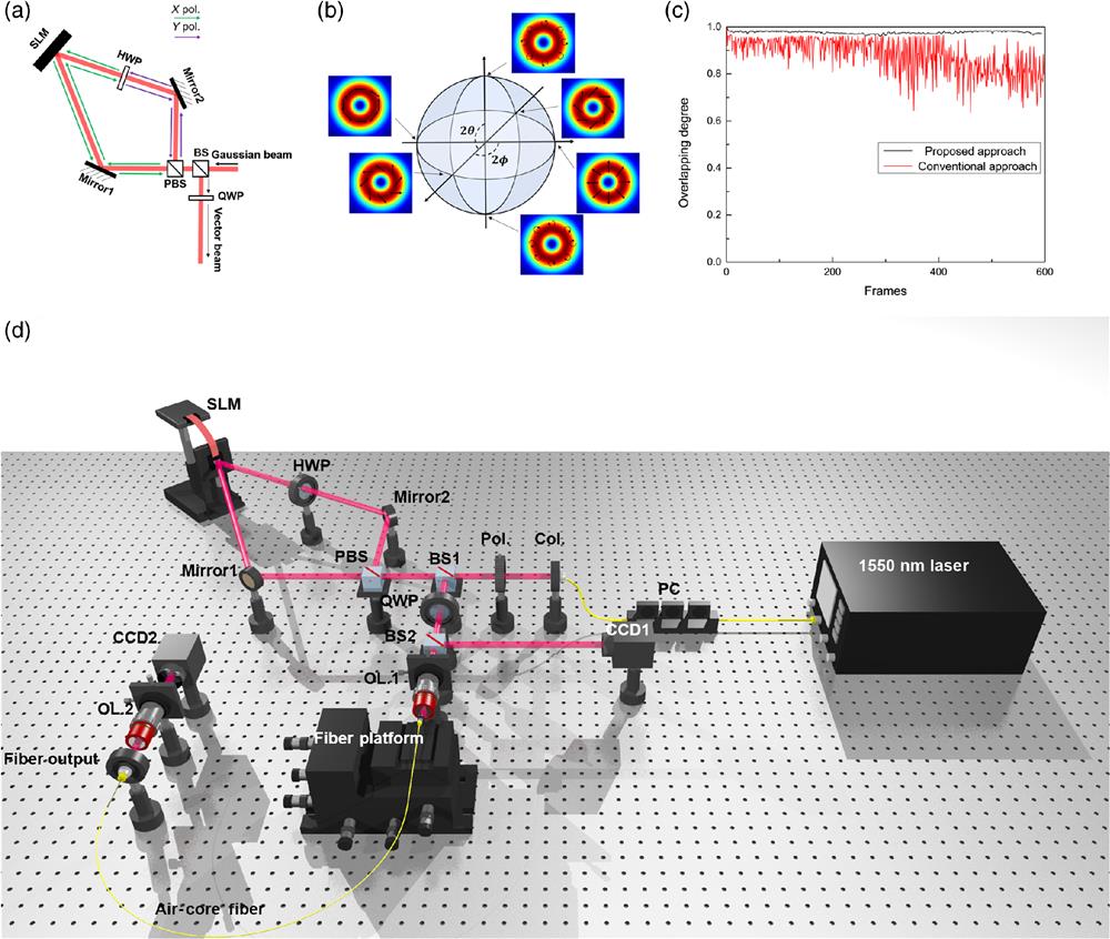
Fig. 1. (a) Concept of reconfigurable structured light beams generator employing a single SLM loop. (b) HOPS with . (c) Overlapping degree between polarization distributions of vector beams in initial frames and vector beams in subsequent frames. (d) Experimental setup of reconfigurable structured light beams generator and fiber-coupling system. PC, polarization controller; Col, collimator; BS, beam splitter; PBS, polarization beam splitter; HWP, half-wave plate; QWP, quarter-wave plate; OL, objective lens; CCD, charge-coupled device (Video 1, mp4, 12.2 MB [URL: https://doi.org/10.1117/1.APN.2.3.036015.s1; Video 2, mp4, 12.1 MB [URL: https://doi.org/10.1117/1.APN.2.3.036015.s2).
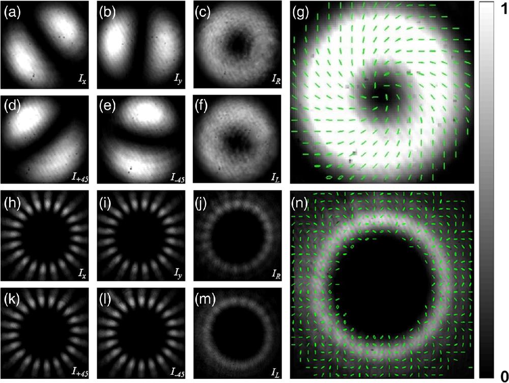
Fig. 2. Polarization reconstruction of cylindrical vector beams. Measured intensity profiles of a vector beam with mode order after propagating through (a) an -polarized polarizer; (b) a -polarized polarizer; (c) a directional QWP and an -polarized polarizer; (d) a polarizer; (e) a polarizer; (f) a directional QWP and a -polarized polarizer; (g) intensity profile and polarization distribution of the vector beam with mode order . Measured intensity profiles of a vector beam with mode order after propagating through (h) an -polarized polarizer; (i) a -polarized polarizer; (j) a directional QWP and an -polarized polarizer; (k) a polarizer; (l) a polarizer; (m) a directional QWP and a -polarized polarizer; (n) intensity profile and polarization distribution of the vector beam with mode order .
Fig. 3. Intensity profiles and polarization distributions of diverse seventh-order structured light beams generated in free space. (a), (b) -polarized OAM beams, insets are interference intensity profiles of them. (c), (d) -polarized LP beams. (e), (f) Circularly polarized OAM beams, insets are interference intensity profiles of them. (g), (h) Vector beams. (i)–(l) Four different vector beams; insets are intensity profiles of vector beams passing through different directional polarizers.
Fig. 4. Coupling losses of the fourth to seventh OAM and vector beams. RCP, right circular polarization; LCP, left circular polarization; and XP, polarization.
Fig. 5. Diverse seventh-order structured light beams after 5-m air–core fiber transmission, insets above figures (a)–(d) are their interference intensity profiles, respectively. (a), (b) -polarized OAM beams; (c), (d) circularly polarized OAM beams; and (e)–(h) vector beams.