
Jiale Yong, Dong Wu. Bioinspired Controlling the Surface Wettability of Materials by Femtosecond Laser: Current Progress and Challenges (Invited)[J]. Chinese Journal of Lasers, 2024, 51(1): 0102002
- Chinese Journal of Lasers
- Vol. 51, Issue 1, 0102002 (2024)
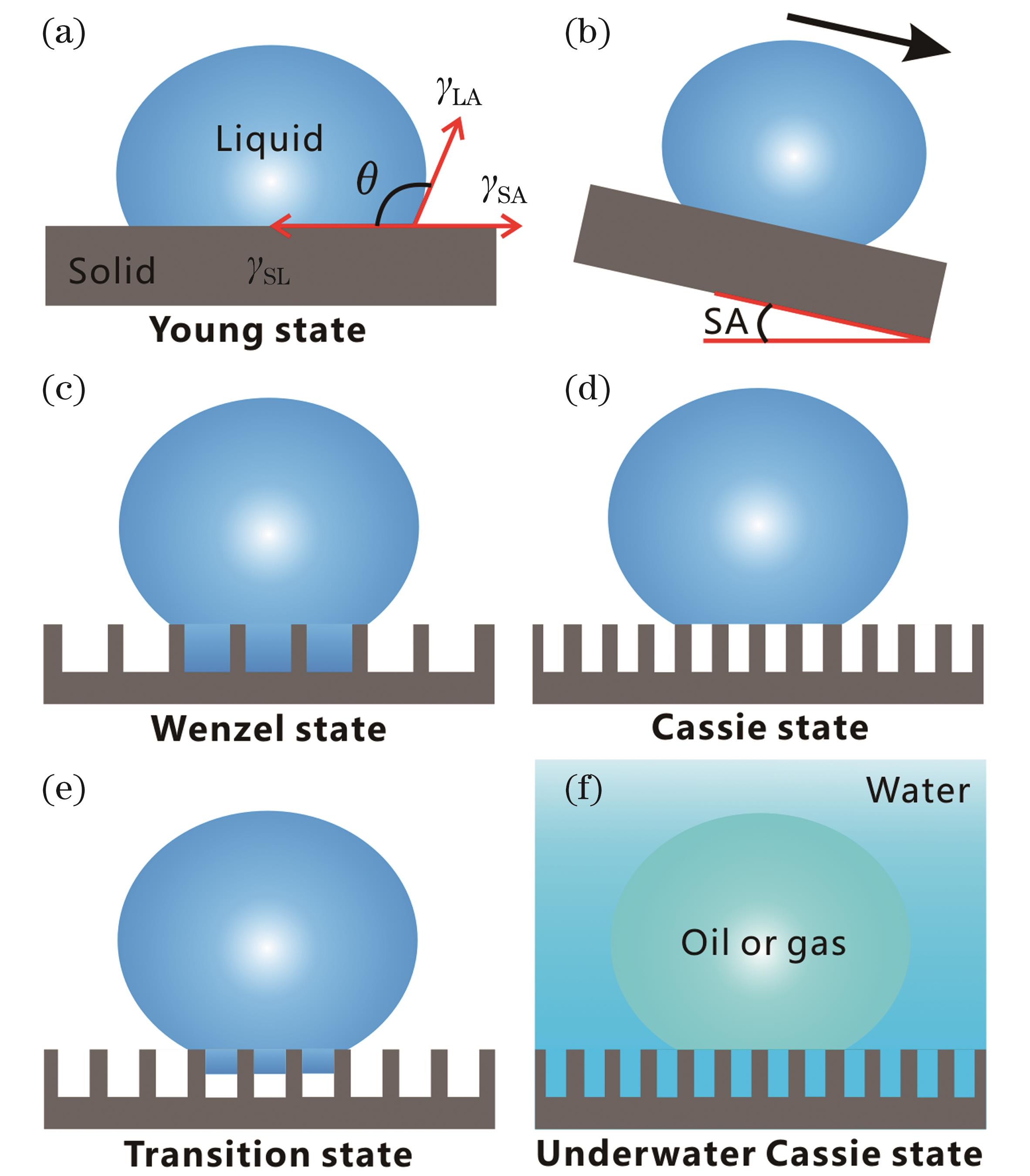
Fig. 1. Basic concepts related to surface wettability and several typical wettability models. (a) Droplet on smooth surface and contact angle (θ); (b) Sliding angle (SA); (c)-(e) Droplet contact on rough microstructure: Wenzel contact state (c), Cassie contact state (d), and Wenzel-Cassie transition contact state (e); (f) Underwater Cassie contact state
![Typical femtosecond laser processing systems. (a) Machining system based on the high-speed scanning galvanometer[70]; (b) combination of an ordinary lens and a two-dimensional moving platform[71]; (c) combination of a microscopic objective lens and a three-dimensional mobile platform[72]; (d) line-by-line laser scanning manner; (e) schematic diagram of femtosecond laser interaction with matter](/richHtml/zgjg/2024/51/1/0102002/img_02.jpg)
Fig. 2. Typical femtosecond laser processing systems. (a) Machining system based on the high-speed scanning galvanometer[70]; (b) combination of an ordinary lens and a two-dimensional moving platform[71]; (c) combination of a microscopic objective lens and a three-dimensional mobile platform[72]; (d) line-by-line laser scanning manner; (e) schematic diagram of femtosecond laser interaction with matter
Fig. 3. Various two-dimensional and three-dimensional patterned microstructures prepared by femtosecond laser processing[76-77]
Fig. 4. Endowing different hydrophilic substrates with superhydrophilicity by femtosecond laser processing. (a)-(d) Hierarchical micro/nanostructures on platinum sheet prepared by laser ablation[83]; (e) droplet spreading out on the laser-structured platinum surface[83]; (f) femtosecond laser-induced microstructure on the silicon surface[84]; (g) droplet spreading out on the structured silicon surface[84]; (h) femtosecond laser-induced microstructure on the glass surface[85]; (i) droplet spreading out on the structured glass surface[85]
Fig. 5. Superhydrophobicity of lotus leaves[86‑87]. (a) Lotus leaves; (b)(c) surface microstructures on lotus leaf; (d) shape of a water droplet on the lotus leaf; (e) water droplet rolling on the surface of the lotus leaf; (f) diagram of the wetting state of a water droplet on the surface of lotus leaf
Fig. 6. Superhydrophobic PDMS and PTFE surfaces prepared by femtosecond laser. (a)(b) Femtosecond laser-induced microstructures on the PDMS surface[91]; (c) three-dimensional and cross-sectional profiles of the microstructures on the PDMS surface[91]; (d) water droplet on the structured PDMS surface[91]; (e)-(g) femtosecond laser-induced microstructures on the PTFE surface[92]; (h) wettability of the structured PTFE surface after femtosecond laser processing, including droplet shape and rolling moment[92]; (i) rolling process of a water droplet on the superhydrophobic PDMS surface with tilt angle of 1°[91]; (j) continuous rebounding process of a water droplet on the superhydrophobic PTFE surface[92]
Fig. 7. Superhydrophobic micro/nanostructures on silicon surface prepared by femtosecond laser in SF6 active gas environment. (a)(b) Femtosecond laser-induced micro/nanostructures[95]; (c) water droplet on the smooth silicone surface modified with fluorosilane[95]; (d) water droplet on the fluorosilane-modified laser-structured silicon surface[95]; (e) femtosecond laser-prepared superhydrophobic black silicon surface[96]; (f) water droplet on the superhydrophobic black silicon[96]; (g)(h) micro/nanostructures hierarchical structures on black silicon surface[96]
Fig. 8. Superhydrophobic micro/nanostructure on silicon surface obtained by femtosecond laser processing in air environment[101]. (a)(b) Femtosecond laser-induced periodic micromountain array microstructure; (c) nanostructures on the micromountain surface; (d) cross-sectional microstructure; (e)(f) shape of water droplet on the laser-prepared superhydrophobic surface
Fig. 9. Different superhydrophobic metal surfaces prepared by femtosecond laser, where the insets show the shape of a water droplet on the corresponding surface. (a) The laser-induced periodic nanoripples on stainless steel surface prepared at low laser energy density[102]; (b) micro/nanoscale hierarchical structure on stainless steel surface prepared at high laser energy density[102]; (c) black platinum surface prepared by femtosecond laser processing[103]; (d)-(f) femtosecond laser-induced micro/nanostructures on the platinum surface[103]; (g)(h) femtosecond laser-induced micro/nanostructures on copper (g) and titanium (h) surfaces[103]; (i) water resistance of superhydrophobic black metals prepared by femtosecond laser[103]; (j) femtosecond laser-prepared hierarchical ZnO microstructure on zinc surface[104]
Fig. 10. Transparent superhydrophobic glass surface prepared by femtosecond laser[106]. (a) Hierarchical micro-well array structure prepared by femtosecond laser; (b) shape of a water droplet on the superhydrophobic glass; (c)(d) high transparency of the superhydrophobic glass
Fig. 11. Superoleophobic surface of springtail and the importance of re-entrant microstructure for achieving superoleophobicity. (a) Springtail[116]; (b)(c) micro/nanostructures on the surface of Springtail skin[116]; (d)-(f) wetting states of low surface-tension liquids on different types of microstructures[35]
Fig. 12. In-air superoleophobic surfaces prepared by femtosecond laser. (a) Three-level re-entrant microstructures prepared by femtosecond laser two-photon polymerization[117]; (b)(c) superoleophobic structures prepared on silicon wafer (b) and polyimide film (c), and the insets show the surface rejection to ferfluorooctane fluid[117]; (d) schematic diagram of the preparation of mushroom-like microstructure based on the laser-induced self-growth process[118]; (e) self-growth process of re-entrant microstructures[118]; (f) morphology of the prepared mushroom-like microstructure[118]; (g) superoleophobicity of the self-grown re-entrant microstructures[118]; (h) the process of preparing superoleophobic microstructures in combination with femtosecond laser ablation and chemical etching[119]; (i)(j) resultant micro/nanostructures[119]; (k) superoleophobicity of the resultant surface[119]
Fig. 13. Underwater superoleophobicity of fish scales. (a) Fish scales[20]; (b)-(d) microstructures on the surface of fish scales[20,87]; (e) oil droplet on the surface of fish scales underwater[20]; (f) contact model between oil droplet and the microstructure on fish scales surface underwater
Fig. 14. Underwater superoleophobicity of the femtosecond laser-structured silicon surface[121]. (a) Water droplet on the untreated surface in the air; (b) water droplet on the laser-structured surface; (c) underwater oil droplet on the untreated surface; (d) underwater oil droplet on the laser-structured surface ; (e) the process of underwater oil droplet rolling on the structured surface
Fig. 15. Transparent underwater superoleophobic silica glass prepared by femtosecond laser[123]. (a) Photo of laser-treated glass sheet; (b)-(d) femtosecond laser-induced surface nanostructures; (e) underwater transparency of the superoleophobic glass sheet; (f) underwater oil droplet on the laser-structured glass surface
Fig. 16. Endowing titanium surface with underwater superoleophobicity by femtosecond laser ablation[77]. (a)-(d) Laser-induced hierarchical micro/nanostructures on titanium surface; (e) water droplet wetting the structured titanium surface in air; (f) underwater oil droplet on the structured titanium surface
Fig. 17. Femtosecond laser-prepared micro/nanostructures on different metal surfaces and their underwater superoleophobicity[126], where the insets show the shape of underwater oil droplets on the corresponding structured surface
Fig. 18. Underwater superaerophobicity of fish scales and underwater superaerophilicity of lotus leaves[87]. (a) Underwater bubble on a fish scale; (b) rolling process of a bubble on the tilted fish scale; (c)-(f) reason for underwater superaerophobicity of fish scales; (g) the process of a bubble being adsorbed by a lotus leaf in the water; (h)-(k) reason for underwater superaerophilicity of lotus leaves
Fig. 19. Underwater superaerophobicity of silicon surface and underwater superaerophilicity of PDMS surface achieved by femtosecond laser processing[87]. (a)(b) Femtosecond laser-induced microstructures on silicon surface; (c) underwater bubble on the structured silicon surface; (d) the process of a water droplet rapidly wetting the structured silicon surface; (e) the process of a bubble rolling off the structured silicon surface in the water; (f)(g) femtosecond laser-induced microstructures on PDMS surface; (h) a water droplet on the structured PDMS surface; (i) the process of a water droplet rolling off the structured PDMS surface; (j) the process of an underwater bubble contacting the structured PDMS surface and spreading out
Fig. 20. Bubble interception effect of underwater superaerophobic porous membrane[87]. (a) Micro/nanostructure of the structured porous aluminum film; (b) continuous release of tiny air bubbles beneath the porous membrane in the water; (c) principle of the bubble interception function of the underwater superaerophobic porous membrane
Fig. 21. Bubble permeability effect of underwater superaerophilic porous membrane[87]. (a) Micro/nanostructure of the structured porous PTFE membrane; (b) continuous release of tiny air bubbles beneath the porous membrane in the water; (c) schematic diagram of underwater bubbles passing through the superaerophilic porous membrane
Fig. 22. Slippery property of Nepenthes surface and the preparation of slippery surfaces by femtosecond laser. (a) Nepenthes[139]; (b)(c) microstructures on the Nepenthes surface; (d) the process for preparing slippery surfaces on hydrophobic PTFE porous fabrics[21]; (e) wetting model of a liquid droplet on a slippery surface; (f) preparation process of slippery surface based on femtosecond laser-induced porous microstructures[141]
Fig. 23. Slippery structure prepared by femtosecond laser on PA surface[140]. (a) Femtosecond laser-induced porous network microstructure; the process of a water droplet (b) and an n-hexadecane droplet (c) sliding off the prepared slippery surface; (d) droplets of various liquids sliding off the slippery surface; (e) self-repairing ability of the slippery surface
Fig. 24. Femtosecond laser-prerpared slippery structure on NiTi alloy surface[142]. (a)(b) Femtosecond laser-induced porous microstructure on NiTi alloy surface; (c) sliding process of a water droplet on the prepared slippery metal surface; (d) sliding process of a blood droplet on the as-prepared slippery surface; (e) sliding process of a blood droplet on the untreated NiTi alloy surface
Fig. 25. Preparation of slippery structure on quartz glass by femtosecond laser wet etching[144]. (a) Preparation process of the slippery surface; (b) liquid-storage structure prepared by femtosecond laser; (c) schematic diagram of slippery surface autocrine lubricant; (d) statistics on the number of droplets allowed to slide off; (e) comparison of droplets after 200 slides on an ordinary slippery glass surface and on a compartment-structured slippery surface
Fig. 26. Endowing stainless steel with underwater superpolymphobicity by femtosecond laser processing[72]. (a)-(c) Femtosecond laser-induced hierarchical micro/naostructures on stainless steel; (d) in-air polymer droplet on the untreated stainless steel surface; (e) underwater polymer droplet on the untreated surface; (f) in-air polymer droplet on the laser-structured surface; (g) underwater polymer droplet on the laser-structured surface; (h) superhydrophilicity of the laser-structured surface; (i) moving a polymer droplet to contact the structured surface and leave in the water
Fig. 27. Contact between an underwater polymer droplet and superpolymphobic microstructure[72]. (a) Light-transmission photography of an underwater polymer droplet on the laser-structured stainless steel surface; (b)(c) SEM images of PDMS droplet after solidification; (d) formation mechanism of underwater superpolymphobicity
Fig. 28. Endowing different materials with underwater superpolymphobicity by femtosecond laser[146]. (a)-(d) Underwater superpolymphobicity of silicon (a), glass (b), aluminum (c), and copper (d) surfaces. First line: laser-induced microstructures on different materials surface; second line: wettability of a water droplet on untreated materials surface, showing intrinsic hydrophilicity of the untreated surfaces; third line: shape of underwater polymer droplet on the structured surfaces. (e) Underwater shapes of silicone oil, epoxy resin, and polybutadiene droplets on the laser-structured stainless steel surface
Fig. 29. Design of the adhesion between polymer and solid substrate based on the underwater superpolymphobic microstructures prepared by femtosecond laser[147]. (a) Three-dimensional profile of the laser-written microgroove on glass surface; (b)(c) laser-induced micro/nanostructures; (d) underwater polymer droplet on the laser-structured glass surface; (e)-(j) the process for preparing microchannels by designing underwater superpolymphobic microstructures; (k)(l) microchannels formed between cured PDMS layer and the glass substrate; (m)(n) simple “T”-shaped microfluidic system
Fig. 30. Design of polymer shape by using femtosecond laser-prepared underwater superpolymphobic microstructure[72]. (a)-(h) The process for the preparation of polymer microlenses based on the underwater superpolymphobicity; (i) 3D profile of the prepared microlens; (j)(k) schematic drawing of the device for testing the imaging ability of a lens and the imaging effect
Fig. 31. Supermetalphobicity of the femtosecond laser-induced micro/nanostructures on silicon surface[152]. (a)(b) Micro/naostructure on silicon surface induced by laser; (c)-(e) water droplet and liquid metal droplet on the smooth silicon surface; (f)-(h) water droplet and liquid metal droplet on the laser-structured silicon surface; (i)-(k) water droplet and liquid metal droplet on the fluorosilane-modified structured silicon surface
Fig. 32. Comparison of adhesive forces of liquid metal droplets on different types of surfaces[152]
Fig. 33. Formation cause of supermetalphobicity of the femtosecond laser-prepared microstructures[152]. (a)-(c) A water droplet and a liquid metal droplet on the high-surface-energy (inherently hydrophilic) substrate; (d)-(f) a water droplet and a liquid metal droplet on the low-surface-energy (inherently hydrophobic) substrate; (g) feasibility analysis of liquid metal penetration into uniform deep microholes
Fig. 34. Patterning of liquid metals based on supermetalphobicity[156]. (a)(b) Mophology and supermetalphobicity of the femtosecond laser-induced microstructure on the PDMS membrane; (c) the process of preparing liquid metal pattern; (d) different liquid metal patterns; (e)(f) microheater consisting of a simple liquid metal circuit; (g)(h) flexible microstrip patch antenna based on liquid metal pattern
Fig. 35. High adhesion of red rose petals to water droplets[158]. (a) Red rose petals; (b)(c) surface microstructure on red rose petal; (d) shape of a water droplet on the petal; (e) water droplet adhering to upside-down petal; (f) contact model between a water droplet and the surface microstructure of red rose petals
Fig. 36. Achievement of controllable adhesion based on the patterned structures designed by femtosecond laser. (a)(b) Laser-prepared patterned structure on PDMS surface[90]; (c) contact angle and sliding angle of water droplets on different patterned surfaces[90]; (d)-(g) superhydrophobicity of the patterned structures and sliding angle of a water droplet[90]; (h) different patterned microstructures prepared by laser on glass surface[124]; (i) contact angle and sliding angle of underwater oil droplets on different patterns[124]; (j) 3D contact model of an underwater oil droplet with a patterned structure[124]
Fig. 37. Femtosecond laser-induced superhydrophobic micro/nanostructures with different morphologies on PTFE surface and their adjustable adhesion[93]. Average distance of the laser pluse-ablated pits: (a) 4 µm, (b) 10 µm, (c) 11 µm, and (d) 18 µm
Fig. 38. Morphology and controllable oil-adhesion of the femtosecond laser-prepared microstructures on glass surface[124]. (a) Laser pulse-ablated craters overlapping heavily to form uniform micro/nanostructure; (b) laser pulse-ablated craters are overlapping slightly and ablation craters can be faintly seen; (c) laser pulse-ablated craters separating from each other with unablasted areas between pits. The first three columns show the laser-induced microstructures, the fourth column shows the wettability state of underwater oil droplets, and the insets show the wettability of underwater oil droplets on the corresponding surfaces
Fig. 39. Anisotropic wettability of rice leaf surfaces[161]. (a) Rice leaves; (b) micro/nanostructures on the the surface of rice leaves; (c)(d) submillimeter grooves on the surface of rice leaves; (e) contact angles along the directions perpendicular and parallel veins; (f) sliding angles along the directions perpendicular and parallel veins
Fig. 40. Anisotropic wettability of the femtosecond laser-written parallel microgroove array[91]. (a) Morphology of the microgroove array; (b) top view of a water droplet on the microgroove array; (c)(d) different contact angles of water droplets along the directions parallel and perpendicular to grooves; (e)(f) different sliding angles of water droplets along the directions parallel and perpendicular to grooves
Fig. 41. Anisotropic wettability of the grooves etched by femtosecond laser. (a) Superhydrophobic groove array prepared by laser on copper surface[162]; (b) three-dimensional morphology and cross-sectional profile of the groove structure on the copper surface[162]; (c) different sliding angles of droplets rolling along the directions parallel and perpendicular grooves[162]; (d) underwater superoleophobic grooves prepared by laser etching on the PDMS surface[164]; (e) three-dimensional morphology and cross-sectional profile of the groove structure on the PDMS surface[164]; (f) anisotropic rolling property[164]; (g) different situations of underwater oil droplets on the laser-etched superoleophobic grooves[164]
Fig. 42. Unidirectional adhesion of butterfly wings and filefish skin to water droplets and underwater oil droplets. (a) Butterfly[165]; (b)(c) microstructure on butterfly wings[165]; (d) different adhesion of droplets on butterfly wings in opposite directions[165]; (e) mechanism of unidirectional adhesion on butterfly wings[165]; (f) filefish[166]; (g) microstructures on the skin of the filefish[166]; (h) underwatrer oil droplet on the skin of the filefish[166]; (i) different sliding angles of underwater oil droplets on the skin of the filefish along opposite directions[166]
Fig. 43. Three-directional anisotropic wettability of step-shaped groove array prepared by femtosecond laser etching[168]. (a) Step-shaped grooves; (b) different sliding angles of water droplets in three different directions; (c) water droplet rolling in the direction parallel to grooves; (d) water droplet rolling in the direction of the lower step; (e) water droplet rolling in the direction of the upper step; (f) directional manipulation of microfluid
Fig. 44. Vibration-assisted directional droplet transport on the femtosecond laser-written inclined microwall array[169]. (a) Diagram of laser processing; (b) morphology of the inclined microwall array; (c) horizontal vibration perpendicular to the direction of the microwall; (d) horizontal vibration parallel to the direction of the microwall; (e) vibration perpendicular to the sample surface
Fig. 45. Photoresponsive reversible wettability transformation of the rough TiO2 surface microstructure prepared by femtosecond laser[77]. (a)-(d) Wettability of a water droplet and an underwater oil droplet on the structured surface after dark storage and UV light irradiation; (e) repeatability of reversible wettability transformation; (f)-(k) underlying mechanism of wettability reversible transformation
Fig. 46. pH-responsive switchable wettability of the femtosecond laser-designed surface[171]. (a) Preparation process of the pH-responsive wettability surface; (b) femtosecond laser-induced micro/nanostructure on the copper surface; (c) different wettabilities of acidic and alkaline droplets on the structured surface; (d) different oil wettabilities of the prepared surface in acidic and alkaline solutions; (e)-(h) pH-responsive oil wettability switching mechanism of the structured surface in liquid environment
Fig. 47. Shape memory microstructure prepared by femtosecond laser and its switchable wettability[107]. (a) Schematic diagram of the method of changing microscopic morphology; (b) femtosecond laser-etched micropillar array; (c) inclined micropillar array; (d) switching mechanism of the micropillars; (e)-(f) wetting state of a droplet on vertical and inclined micropillars
Fig. 48. Reversible manipulation of an underwater oil droplet picking up and releasing between the femtosecond laser-prepared underwater superoleophobic surfaces based on regulating water density[75]. (a) Schematic diagram of the installation; (b) the process of picking oil droplet up by increasing the density of the aqueous solution and releasing droplet by diluting the aqueous solution; (c) principle of picking up and releasing droplet by adjusting solution density; (d) repeatability
Fig. 49. Reversible switch between underwater superaerophilicity and superaerophobicity on the femtosecond laser-prepared superhydrophobic surface based on the method of alcohol pre-wetting and drying recovery[136]. (a) Micro/nanostructures prepared by femtosecond laser on aluminum surface; (b)(c) superhydrophobicity of the structured aluminum surface after fluorosilane modification; (d)-(g) the process of realizing reversible transition between underwater superaerophilicity and superaerophobicity
Fig. 50. Self-cleaning function of superhydrophobic surfaces and underwater superoleophobic surfaces prepared by femtosecond laser. (a) Self-cleaning schematic of superhydrophobic surfaces[91]; (b)(c) rolling droplets cleaning contaminants on the superhydrophobic silicon surface[101]; (d)(e) rolling droplets cleaning contaminants on the superhydrophobic polymer surface[91]; (f) the method and process for removing oil contaminants from underwater superoleophobic surfaces[179]
Fig. 51. Multifunctional droplet manipulation based on special wetting surfaces prepared by a femtosecond laser. (a) Lossless droplet transport[90]; (b) rapid droplet capture and localization[90]; (c) droplet directional transport[107]; (d) directional self-cleaning[107]; (e) droplet patterning[76]; (f) droplet-based microchemical reactors[76]; (g) gas sensing[76]; (h) remotely laser-controlled droplet release[180]
Fig. 52. Liquid lens array prepared based on liquid patterning method[181]. (a) The idea of realizing liquid lenses; (b) circular array pattern prepared by femtosecond laser on glass surface; (c)-(e) femtosecond laser-induced micro/nanostructures; (f) formed droplet array; (g) imaging capability of droplet lens array
Fig. 53. Buoyancy enhancement effect of superwetting materials prepared by femtosecond laser. (a) Enhanced buoyancy in nature and life[56]; (b) upper surface microstructure of a femtosecond laser-prepared superhydrophobic boat[56]; (c) large load capacity of a superhydrophobic wafer boat[57]; (d) contact between the superhydrophobic boat and the water surface[57]; (e) reason for enhanced buoyancy[57]; (f) the superhydrophobic sandwich (aluminum-air-aluminum) structure allowing the metal aluminum sheet to float to the water surface[57]; (g) underwater superoleophobic metal sheet floating stably on the oil surface (underwater)[182]
Fig. 54. Superwetting needles prepared by femtosecond laser for releasing tiny droplets or bubbles[134]. (a) Needle structure before laser treatment; (b) femtosecond laser-induced microstructure on the end face of the needle; (c) comparison of droplets released by hydrophilic, superhydrophilic, and superhydrophobic needles; (d) comparison of oil droplets released by underwater oleophobic, superoleophobic, and superoleophilic needles; (e) comparison of bubbles released by underwater aerophobic, superaerophobic, and superaerophilic needles
Fig. 55. Achievement of oil-water separation based on the superhydrophobic or underwater superoleophobic porous membranes prepared by femtosecond laser. (a) The structure of superhydrophobic porous PTFE membrane[92]; (b) oil-water separation by using superhydrophobic porous PTFE membrane[92]; (c) oil-water separation principle based on superhydrophobic porous membrane; (d) underwater superoleophobic porous aluminum membrane[184]; (e) oil-water separation by using underwater superoleophobic porous aluminum membrane[184]; (f) oil-water separation principle based on underwater superoleophobic porous membrane
Fig. 56. Separation of water and liquid polymers by using femtosecond laser-structuerd underwater superpolymphobic metal mesh[186]. (a)(b) Laser-induced nanostructure on the surface of stainless steel mesh; (c) superhydrophilicity of structured metal mesh; (d) underwater superpolymphobicity of the structured metal mesh; (e) water-polymer separation based on filtration manner; (f) removal of liquid polymers floating on the surface of the water based on fishing process
Fig. 57. Realization of water/gas separation based on the underwater superaerophilic and superaerophobic microstructures. (a) Femtosecond laser-prepared micro/nanostructures on the surface of porous PDMS films[187]; (b) schematic diagram of the underwater bubble collection device[187]; (c) a bubble collection device based on underwater superaerophilic porous PDMS films[187]; (d) the process of collecting air bubbles in water[187]; (e) microstructures prepared by femtosecond laser on the surface of stainless steel mesh[189]; (f) schematic diagram and working principle of the device for removing bubbles in the water pipelines[189]; (g) the process of removing air bubbles from the water flow[189]
Fig. 58. Anti-icing and icephobic functions of the superhydrophobic and the slippery surfaces prepared by femtosecond laser. (a) Condensation process of tiny droplets at the top of superhydrophobic microcones[191]; (b) upward migration of secondary droplets between conical microstructures[191]; (c) merge of secondary droplet and primary large droplet as well as droplet jumping[191]; (d) comparison of water droplets freezing on the untreated, superhydrophobic, and slippery stainless steel surfaces[192]; (e) ice adhesion strength comparison on the untreated, superhydrophobic, and slippery stainless steel surfaces[192]; (f) schematic diagram of ice formation and de-icing on a slippery surface[192]
Fig. 59. Corrosion resistance of femtosecond laser-structured metal surfaces. (a) Preparation process of superhydrophobic and slippery surfaces on aluminum substrate by femtosecond laser[193]; (b) wettability of the prepared superhydrophobic and slippery surfaces[193]; (c) surface microstructures after corrosion in simulated seawater for 24 h[193]; (d) comparison of corrosion resistance of different surfaces[193]; (e)-(i) corrosion resistance of slippery NiTi alloy[195]
Fig. 60. Drag reduction function of superhydrophobic and slippery surfaces prepared by femtosecond laser. (a)-(c) Drag reduction principle of superhydrophobic surface; (d) drag reduction diagram of the slippery surface[197]; (e)(f) drag reduction performance of slippery surface[197]
Fig. 61. Superwetting fog-collection device prepared by femtosecond laser. (a) Surface structure of the two sides of the Janus porous film prepared by femtosecond laser[198]; (b) femtosecond laser-drilled conical microholes[198]; (c) comparison of fog collection performance of Janus porous membranes[198]; (d) comparison of fog collection efficiency[198]; (e) self-transport of water droplet on the femtosecond laser-designed vein structure[200]; (f) fog collection based on superhydrophilic-superhydrophobic vein network structure[200]
Fig. 62. Various bubble manipulation applications enabled by femtosecond laser-prepared underwater aerofluidic systems[70]. (a) Gas merging; (b) gas aggregation; (c) gas splitting; (d) gas arrays; (e) gas-gas microreaction based on bubbles; (f) gas-liquid microreaction; (g)(h) integration of underwater aerofluidic devices with traditional liquid microfluidic system
Fig. 63. Various liquid-metal flexible circuits prepared by femtosecond laser. (a) Liquid metal pattern[152]; (b) simple liquid-metal circuit affixed to a finger[152]; (c) liquid metal-based sensor sensing ants walking[203]; (d) the process of preparing a fully flexible tactile sensor based on a liquid-metal sandwich layer structure[204]; (e) flexible tactile sensor for monitoring various human physiological and motor signals[204]
Fig. 64. Inhibition of cell growth by superhydrophobic and slippery surfaces prepared by femtosecond laser. (a) Different micro/nanostructures on silicon surface prepared by femtosecond laser[205]; (b) wettability change of water droplets[205]; (c) fibroblast growth[205]; (d)-(f) comparison of the growth of C6 glioma cells on untreated smooth PET surface (d), rough PET surface (e), and slippery PET surface (f)[141]
Fig. 65. Anticoagulant property of slippery surface prepared by femtosecond laser in vivo[195]. (a) Schematic diagram of experimental test; (b)(c) comparison of fluorescence microscopy of the untreated NiTi alloy (b) and the SLACS (c) after implantation for different time; (d)(e) comparison of microstructures of the untreated NiTi alloy (d) and the SLACS (e) after implantation for different time; (f)(g) macromorphology and tissue biopsies of biofilms adhering to the untreated metal surface after 5 weeks implantation; (h) macroscopic morphology of the SLACS after 5 weeks implantation
Fig. 66. Sewage purification based on superhydrophilic microstructure prepared by femtosecond laser[206]. (a) Schematic diagram of sewage purification device; (b) liquid evaporation and temperature on the surface of the laser-structured aluminum sheet under sunlight; (c) the process of temperature rising on the metal surface; (d) comparison of water evaporation efficiency; (e) comparison of different pollutants contents before and after sewage purification
Fig. 67. SERS detection based on superwetting composited patterns designed by femtosecond laser[208]. (a) Diagram of superhydrophobic/superhydrophilic composited surface and laser processing system; (b) schematic diagram of Raman signal enhancement based on droplet concentration; (c) preparation process of superhydrophobic/superhydrophilic structures; (d) droplet concentration process; (e) fluorescence microscopy of the distribution of the substance to be detected after concentration; (f) diagram of the concentration process of the detecting substance; (g) Raman spectra of different concentrations of R6G

Set citation alerts for the article
Please enter your email address
© Copyright 2018-2021 | Chinese Laser Press. All Rights Reserved 沪ICP备15018463号-20