
Hengrui Guan, Fenghua Zheng, Wenxiang Li, Chao Kang, Yongxing Yang, Jinpeng Li. Analysis of Optomechanical Characteristics of Semi-Ellipsoidal Mirrors for Measuring High-Temperature Optical Parameters of Materials[J]. Acta Optica Sinica, 2021, 41(6): 0608002
- Acta Optica Sinica
- Vol. 41, Issue 6, 0608002 (2021)
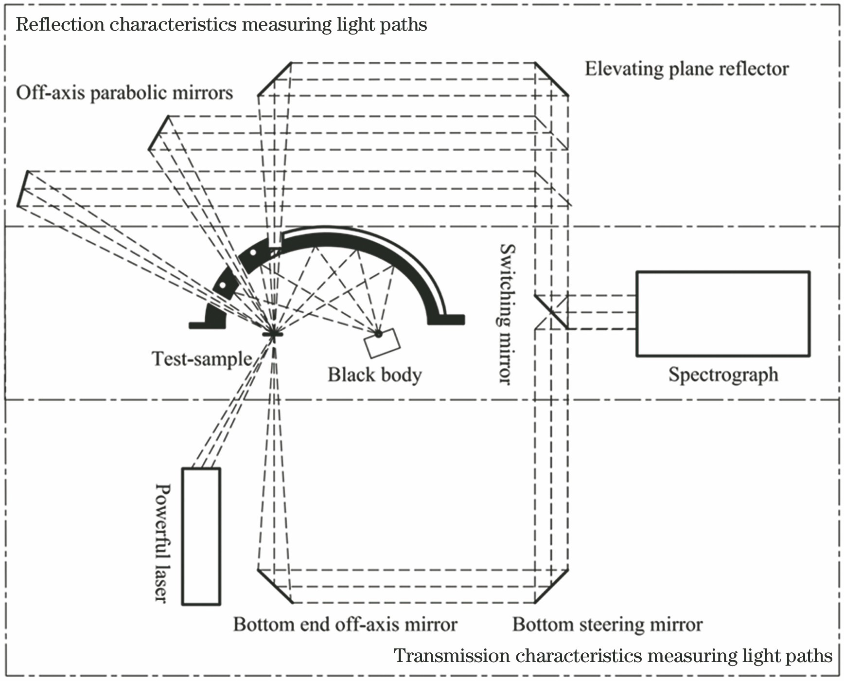
Fig. 1. Light path of device
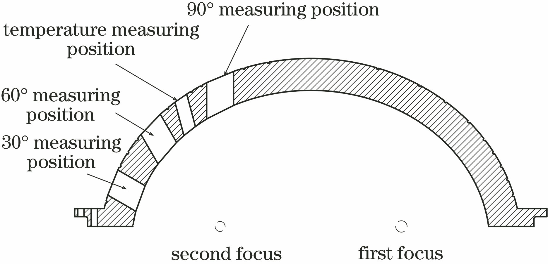
Fig. 2. Diagram of semi-ellipsoidal mirror
Fig. 3. Ray tracing result of semi-ellipsoidal mirror
Fig. 4. Convergent focus spots generated when luminous surface source is located at different positions near focal point. (a) At focus position; (b) at +2.5 mm in x direction; (c) at -2.5 mm in x direction; (d) at +2.5 mm in y direction; (e) at -2.5 mm in y direction
Fig. 5. Irradiance on sample surface from black body radiation sources with different diameters. (a) Black body radiation source with Φ5 mm diameter; (b) black body radiation source with Φ10 mm diameter; (c) black body radiation source with Φ15 mm diameter
Fig. 6. Diagram of finite element modeling of semi-ellipsoidal mirror
Fig. 7. Surface shape changes of semi-ellipsoidal reflector under different temperature loads. (a) 22 ℃; (b) 24 ℃; (c) 26 ℃; (d) 28 ℃; (e) 30 ℃
Fig. 8. Irradiance formed by the black body radiation source on the surface of the sample to be tested at 30 ℃
Fig. 9. Initial detection surface shape of the reflective surface of the semi-ellipsoidal mirror
Fig. 10. Final inspection surface shape of semi-ellipsoidal mirror
|
Table 1. Optical tracing parameters of semi-ellipsoid mirror
|
Table 2. Light energy utilization when point light source is located at different positions
|
Table 3. Deformation of working surface of semi-ellipsoidal reflector at different temperatures
|
Table 4. Detection results of inner surface of semi-ellipsoidal mirror

Set citation alerts for the article
Please enter your email address
© Copyright 2018-2021 | Chinese Laser Press. All Rights Reserved 沪ICP备15018463号-20