
Igor V. Minin, Oleg V. Minin, Yinghui Cao, Bing Yan, Zengbo Wang, Boris Luk’yanchuk. Photonic lenses with whispering gallery waves at Janus particles[J]. Opto-Electronic Science, 2022, 1(2): 210008-1
- Opto-Electronic Science
- Vol. 1, Issue 2, 210008-1 (2022)
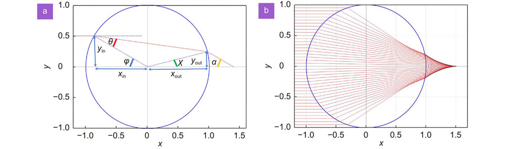
Fig. 1. (a ) Ray tracing for a big particle with radius Rb ) The shape of the caustic from the Eq. (1) for the sphere with n = 1.5 is shown by dashed black line.
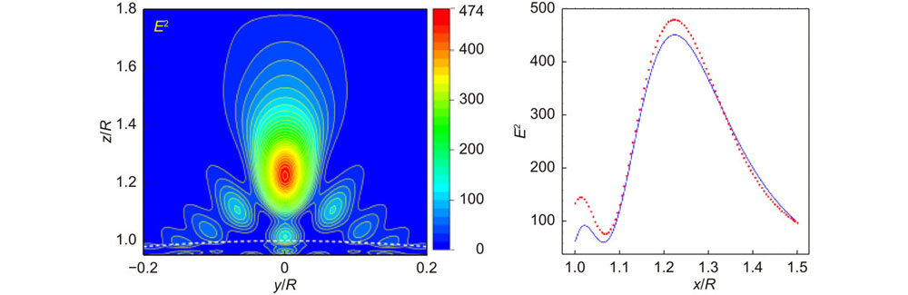
Fig. 2. (a ) Distribution of intensity calculated from the Mie theory with n = 1.5 and q = 70. Such distribution is typical for Bessoid matching solution, see e.g., Fig. 5 in ref.24. (b ) Intensity distribution according to Bessoid approximation24 (solid blue line) and from the Mie theory (dotted red line).
Fig. 3. Amplitudes
The first sharp resonance arise at q by the order of
Fig. 4. (a ) Spherical Bessel function
b ) Spacial distribution of the modulus of the
Fig. 5. Distribution of electric intensity (E/E0)2 within the yz plane of the particle with refractive index n = 1.515 and size parameter q = 11.
Fig. 6. (a ) We introduce the same incidence angle φ and the refraction angle θ as in Fig. 1(a). Here h is the height of truncation normalized to particle radius R. Ray emerges from the sphere after the second refraction with the angle γ follows the Snell’s law sinγ = n sin(φ − θ). The shape of the caustic for the truncated sphere with h = 1 − 1/n and n = 1.5 is shown by dashed black line. The solid green line shows the caustic of the spherical particle with the same refractive index. (b ) The same parameters and the exact solution of the Maxwell equation, corresponding to size parameter q = 2πR/λ = 100.
Fig. 7. Distribution of electric E2 intensity (picures on the top) and magnetic H2 intensity (down pictures) within the cross section of the Janus cylinder with refractive index n = 1.5 (down), n = 1.3 (top), and size parameter q = 5π.
Fig. 8. Maximal field enhancement around the truncated cylindrical versus the depth of truncated element.
Fig. 9. Distribution of the field intensity for a resonant value of truncation (a ) and zoom in (b ) and further (c ).
Fig. 10. Internal and external electric (a ) and magnetic (b ) intensities versus size parameter for the cylinder with fixed truncation parameter h = 0.02. Size parameter q = 32.5 correspnds to radius of the cylinder 2R≈ 10λ.
Fig. 11. Schematic for a lithographic process with truncated cylinders. Here a thin protected layer between the matrix and photoresist plays an important role of anti-reflective coating, depending on the thickness of the coating.


Set citation alerts for the article
Please enter your email address

© Copyright 2018-2021 | Chinese Laser Press. All Rights Reserved 沪ICP备15018463号-20