Igor V. Minin, Oleg V. Minin, Yinghui Cao, Bing Yan, Zengbo Wang, Boris Luk’yanchuk. Photonic lenses with whispering gallery waves at Janus particles[J]. Opto-Electronic Science, 2022, 1(2): 210008-1
Copy Citation Text
We show that electric field on the plane surface of truncated sphere or cylinders (so called Janus particles) have sharp resonances versus the depth of removed segment of a sphere or cylinder. These resonances are related to the excited whispering gallery waves caused by truncation. It is a new mechanism of the field localization. Optimization of this effect for cylinders permits to reach a super resolution in the line thickness, which can be used for contact optical lithography.We show that electric field on the plane surface of truncated sphere or cylinders (so called Janus particles) have sharp resonances versus the depth of removed segment of a sphere or cylinder. These resonances are related to the excited whispering gallery waves caused by truncation. It is a new mechanism of the field localization. Optimization of this effect for cylinders permits to reach a super resolution in the line thickness, which can be used for contact optical lithography.
Introduction
Development of optical lithography with nanoscale resolution has been a long-standing goal for the nanotechnology community1. Among the many suggested methods there were a lithography with transparent dielectric particles which were used as a microscopic lenses2-5. The basic physical features of this technique can be well understood from the Mie theory6 and also from the more complicated problem “particle on surface”7, 8. According to these calculations, a transparent dielectric sphere with a diameter of more than three wavelengths of radiation incident on it can function either as a focusing lens (photon jet mode) or as a resonator concentrating energy in the whispering gallery waves in the wall region9. A similar behavior is shown by a transparent cylinder. The transition from the photon jet mode to the resonator mode with whispering gallery waves occurs when the size of the sphere or the radiation wavelength changes. Both phenomena are perfectly described in the framework of Mie theory, see e.g.10. New phenomena arise in particles in which a segment of a sphere or cylinder is removed (Janus particles11, 12). It is a typical design of solid immersion lens13, 14. It is known that parameters of a photonic jet from a hemisphere (or hemicylinder) can be very different from the parameters of a jet formed by a whole sphere15 or cylinder16.
In the present paper we show that parameter of whispering gallery waves can be also quite different from the whole sphere or cylinder. Optimization of the remote segment thickness permits to create highly localized field distribution. This effect in cylinders can be used for contacting optical lithography with super resolution in the line thickness.
Photonic nanojet: from geometrical optics approximation to the Mie theory
A spherical transparent particle can focus light. This effect has been known for a few millennia: for example, Pliny the Elder (AD 23–AD 79) reported on the incendiary action of glass spheres9. This effect is easy to understand under geometric optics approximation17, 18. The simplest way is to use ray tracing19 and Snell’s law20, 21 (this technique has been known since Kepler). Refracted rays form a caustic, which is presented by parametric equation (here all coordinates
and
are normalized by particle radius,
):
where
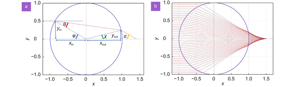
Such caustic is presented by cuspoid curve22, 23, as in Fig. 1. The singularity point (geometrical optics focus24) is situated at
Figure 1.(a) Ray tracing for a big particle with radius Rλ. We introduce the incidence angle φ and the refraction angle θ inside the sphere sinφ = nsinθ. The ray enter into the particle at the point with coordinates yin= tanφ and xin= −cosφ. The angles χ and α are given by χ = 2θ − φ and α = 2φ − 2θ. Two close rays yc and ycc (corresponding to angles φ and φ + δφ) emerged from the sphere after the second refraction are crossing at the caustic point xc= xout + ∂φsinχ/∂φtanα. This yields the Eq. (1) for caustic. (b) The shape of the caustic from the Eq. (1) for the sphere with n = 1.5 is shown by dashed black line.
Thus,
at
and
at
. When
the caustic is situated inside the sphere, this is the case of materials with a high refractive index. Such materials are used in optically resonant dielectric nanostructures25, while materials with a refractive index of less than two9 are the main materials for most optical components (lenses, optical fibers, etc.). This caustic was analyzed in a number of papers due to the problem of photonic nanojet, see ref.9 and references there. From the Eq. (1) one should define the numerical aperture
, where the angle
calculated at the surface of the particle, i.e., at
. This estimation yields
. Maximal field enhancement in the focal point can be estimated as
where
Position of geometrical optics focus can be approximated by
The solution with ray tracing yields just a qualitative picture of light focusing. One can compare this solution with the exact solution which follows from the Mie theory6. However, the approximation of geometrical optics is valid just for sufficiently big size parameter
(here
is radius of the particle and
is radiation wavelength). Thus, exact solution requires the summation of a large number of terms,
𝓁26, in a multipole expansion even for moderate sphere sizes. For such big particles one can use the method of uniform caustic asymptotic18. The lowest nontrivial order correction for the field distribution is related to Bessoid integral. This integral appears naturally in the paraxial approximation24. Results of calculations are shown in Fig. 2.
Figure 2.(a) Distribution of intensity calculated from the Mie theory with n = 1.5 and q = 70. Such distribution is typical for Bessoid matching solution, see e.g., Fig. 5 in ref.24. (b) Intensity distribution according to Bessoid approximation24 (solid blue line) and from the Mie theory (dotted red line).
According to the Mie theory6, 26 the scattering efficiency
(here
is scattering cross section) can be expressed as a sum of electric
𝓁 and magnetic
𝓁 scattering efficiencies associated with the multipolar moment of
𝓁 the order multipoles:
𝓁𝓁𝓁𝓁𝓁𝓁𝓁𝓁𝓁
where the electric
𝓁 and magnetic
𝓁 scattering amplitudes are defined by formulas
𝓁𝓁𝓁𝓁𝓁𝓁𝓁𝓁
with
𝓁 and
𝓁coefficients expressed by
𝓁𝓁𝓁𝓁𝓁𝓁𝓁𝓁𝓁𝓁𝓁𝓁𝓁𝓁𝓁𝓁𝓁𝓁𝓁𝓁
here the functions
𝓁𝓁 and
𝓁𝓁 are expressed through the Bessel and Neumann functions10. We use the subscripts
and
to denote the values referring to the external media and the particle, with refractive indices
and
, respectively. In the expressions above,
and
. The symbol
represents the so-called size parameter, defined as
.
The electric and magnetic fields inside the particle are expressed through the internal scattering amplitudes
𝓁 and
𝓁 given by6
𝓁𝓁𝓁𝓁𝓁𝓁
Although the denominators of these amplitudes are the same as in amplitudes
𝓁 and
𝓁 in Eq. (5), which means that position of these resonances are close, the numerators of Eq. (7) never tends to zero. As a result the values of amplitudes
𝓁 and
𝓁 are not restricted by unity as amplitudes
𝓁 and
𝓁 in Eq. (5), but increase with values of size parameter and refractive index. To compare amplitudes it is convenient to introduce partial internal scattering efficiencies, similar to those in Eq. (4):
𝓁𝓁𝓁𝓁𝓁𝓁
It leads to specific variation of
𝓁 and
𝓁 amplitudes at the big
𝓁 values. Namely, the amplitudes of these functions are quite small up to some threshold values,
, which are of the order of
𝓁10, 27, see an example in Fig. 3. The first narrow resonance at
, where
𝓁, plays a dominant role in the Mie theory. The total electric field
(similar in
) can be presented as a sum of a single resonant term
𝓁𝓁with a narrow spectrum and the field from all other nonresonant terms
𝓁𝓁𝓁 with a broad spectrum. The interference of the signals with a broad and narrow spectums yields the Fano resonance, which produces the narrow resonances in the intensity. These resonances in electric and magnetic fields greatly exceed corresponding resonances in the scattering efficiency10.
Figure 3.Amplitudes
𝓁 and
𝓁 for ℓ = 30 and np= 1.5 versus size parameter q.The first sharp resonance arise at q by the order of
𝓁. Insert shows how the position of the first sharp resonance vary with
𝓁 number.
The electric and magnetic fields can be defined through the derivations of the electric,
𝓁, and magnetic,
𝓁, Debye potentials17. Inside the particle these potentials are presented by17
𝓁𝓁𝓁𝓁𝓁𝓁𝓁𝓁𝓁𝓁𝓁𝓁𝓁𝓁𝓁𝓁
here
is the wave vector inside the particle,
.
From the Eq. (9) one explains the physical origin of the whispering gallery waves (WGW) formation28. Argument spherical Bessel function
𝓁 varies from zero in the center of the particle till parameter
on the surface of the particle. Thus, at big
𝓁 values
𝓁 function is close to zero till to critical value
which is by the order of
𝓁, see in Fig. 4(a). If the first zero of the Bessel function is located near the radius of the sphere, then almost the entire field of this wave will be located in a very narrow region near the surface of the sphere. This is the WGW case. The angular field modulation is presented by Legendre function, see in Fig. 4(b).
Figure 4.(a) Spherical Bessel function
𝓁 at big index
𝓁100028. (b) Spacial distribution of the modulus of the
𝓁 function (9) at
0 and
𝓁30 for
and
.
The WGW can be interpreted as a wave of total internal reflection of the ray propagating along the surface of the dielectric sphere28. However, if the interface has a curvature (as in the case of the sphere), then the internal reflection is not complete: part of the wave still seeps out of the ball out. One can see this leakage in Fig. 4(b). It occurs through the white triangles situated on the surface of the particle. The leakage is the smaller, the larger the radius of the ball in comparison with the wavelength. That is, for the existence of WGW, the sphere must have a rather sick radius in comparison with the wavelength of light, i.e., it needs the condition
. Calculations with the Mie theory show that the WGW structure in the electric field intensity can be seen even at the size parameter by the order of ten, see in Fig. 5.
Figure 5.Distribution of electric intensity (E/E0)2 within the yz plane of the particle with refractive index n = 1.515 and size parameter q = 11.
Janus particle: from geometrical optics to the whispering gallery waves.
One can examine the light focusing by truncated cylinder or a sphere, see in Fig. 6. Truncated segment can be replaced by a similar portion of different material – such structures are called as Janus particles29. We use notation
for the height of truncated segment. In particular case replaced portion can be an air or vacuum. In simulations (here and below) the models were built by using a finite integral technique (FIT) realized in commercial software package - CST Microwave Studio. Tetrahedral meshes and triangular grids were fitted with ‘open space’ boundary condition along all directions (x, y, z) to approach better accuracy for simulation. Mesh sizes were set to λ/15 for particle and λ/10 for background. The ray tracing technique applied for truncated sphere yields the following shape of the caustics:
Figure 6.(a) We introduce the same incidence angle φ and the refraction angle θ as in Fig. 1(a). Here h is the height of truncation normalized to particle radius R. Ray emerges from the sphere after the second refraction with the angle γ follows the Snell’s law sinγ = n sin(φ − θ). The shape of the caustic for the truncated sphere with h = 1 − 1/n and n = 1.5 is shown by dashed black line. The solid green line shows the caustic of the spherical particle with the same refractive index. (b) The same parameters and the exact solution of the Maxwell equation, corresponding to size parameter q = 2πR/λ = 100.
The singularity point this Janus particle situated at
The basic effect with Janus particle is related to variation of focal length in comparison with the initial sphere. For example, the sphere with
has the focal point situated at
. After small truncation with
corresponding Janus particle has a focal point with
, i.e., truncation yields the longer focus. The ray tracing technique19 approximation gave qualitatively correct description of focusing properties of transparent dielectric.
The truncated particle presents a solid immersion lens (SIL) which can overcome diffraction limit13. It could be noted that physical principles of truncated spherical SIL, for which aberration free focusing occurs and also known as Weierstrass SIL, is based on compressing the emitted light into a small NA by decreasing of the refraction angle of the transmitted light, measured from the optical axis. This occurs when the sphere is truncated to a thickness h = r (l + l/n), where r is the radius of the sphere, and h corresponds to the aplanatic focus, see in ref.17 (page 253) and ref.30. Similar SIL have been used in optical microscopes and photolithography31. Analysis of the photonic nanojet with truncated spherical particle shows that the maximal intensity in the focal point is less than those produced by spherical particle, but the effective focal length can be much greater15.
We repeated a similar numerical analysis for a different design of Janus particles and found some new effects. As an example, we show in Fig. 7 the cylindrical Janus particle consisting from two half cylinders with different refractive index:
for the bottom part and
for the upper part. The diameter of a whole cylinder is equal to
. Thus, the size parameter
. At normal condition one can see a usual photon nanojet with maximal field enhancement
at the focal point. A small truncation with
leads to the field redistribution due to strong WGW excitation with maximal field enhancement
. A further truncation with
practically restore the initial photon nanojet. A similar behavior can be seen for magnetic intensity variation.
Figure 7.Distribution of electric E2 intensity (picures on the top) and magnetic H2 intensity (down pictures) within the cross section of the Janus cylinder with refractive index n = 1.5 (down), n = 1.3 (top), and size parameter q = 5π.
An example of truncation effect for the intensity distribution is shown in Fig. 8. Namely, for the cylinder with refractive index
and big size parameter
we can see a number of oscillations with maximal intensity around the particle. These oscillations depend on light polarization and the depth of truncated layer. Amplitudes of these resonances are typically about 10% of average intensity with field enhancement about 25. However, for some small truncation with
we can see in Fig. 8 resonance for TM polarized light with field enhancement in the hot spots on the surface. It looks like resonant excitation of surface electromagnetic wave within the plane disk of the truncated surface. The singularity related to phase discontinuity at the line where the spherical (or cylindrical) surface cross the plane surface leads to change of the Snell’s law to generalized laws of reflection and refraction32. According to this law occurs the variation of critical angles for total internal reflection. At some value of phase gradient there is a critical angle of incidence above which the reflected beam becomes evanescent32. Under the approximation of geometrical optics this phase gradient depends on the thickness h of truncated element and refractive index n. In Fig. 9(c) one can see the result of interference of two evanescent waves. We also found that the efficiency of the excitation of whispering gallery waves strongly depends on the h value.
Figure 8.Maximal field enhancement around the truncated cylindrical versus the depth of truncated element.
Optimization of this effect for cylinders permits to reach a super resolution in the line thickness which can be used for contacting optical lithography
Truncated nanowires for near field optical lithography
The most powerful modern lithographic technique is related to usage of focused electron beams33 or ion beams34 (e.g. a focused helium ion beam35). These techniques permit to realize patterning fidelity at nanometer scale dimensions. However, beam technology is associated with very expensive and complex equipment. In addition, it is rather slow.
Over the past decades, a number of new ideas have been proposed to create a fast-lithographic technique that allows mass production of structures with a scale of tens of nanometers. Among these ideas, for example, an evanescent interferometric lithography36-38 can be mentioned. Other techniques involve laser induced tip-assisted Atomic Force Microscope (AFM)39 or a Near-field Scanning Optical Microscope (NSOM)40, 41. Finally, we should mention ‘plasmon printing’ technology42-44. The later relies on the surface plasmon resonance occurring in metal nanoparticles, which can produce sub-wavelength structures.
Returning to lithography using Janus particles, we note once again the resonance properties of small truncation of the cylinder, see in Fig. 10. Here we show the maximal intensities inside and outside particle. Each resonance corresponds to resonant excitation of whispering gallery waves. Similar resonances existing within the nontruncated particles as well (see e.g., movie in supplementary materials in ref.9). The difference is that in truncated particles these resonances are sharper. We also draw attention to the fact that in Janus particles the magnetic nanojet mode appears to be more contrasting compared to nontruncated particles9. It gave the additional functionality to work with magnetic materials.
Figure 10.Internal and external electric (a) and magnetic (b) intensities versus size parameter for the cylinder with fixed truncation parameter h = 0.02. Size parameter q = 32.5 correspnds to radius of the cylinder 2R≈ 10λ.
Depending on truncation parameter h and radiation wavelength, one can realize situation with a single, double, or quadruple-maximums distributions in the intensity on the plane truncated surface. Having the spacing between cylinders as additional parameter we can imagine lithographic technique schematically presented in Fig.11. The number of cylinders with refracted index
are embedded into matrix with refracted index
. It is equivalent to situation when the cylinders with relative index
are situated in vacuum. The surface of this matrix can be polished to reach a precise truncation.
Figure 11.Schematic for a lithographic process with truncated cylinders.Here a thin protected layer between the matrix and photoresist plays an important role of anti-reflective coating, depending on the thickness of the coating.
We performed a modeling of this technique to analyze the patterning fidelity at nanometer scale dimensions. The length of the lines can be on a scale of centimeters.
Conclusions
A spherical resonator cannot have an infinite quality factor (Q-factor45) due to the violation of the total internal reflection on a curved surface. Recently, many efforts have been made to increase the Q-factor of spherical and dielectric resonators using bound states in continuum46, 47. Our research shows that the use of Janus particles also contributes to an increase in the figure of merit and an increase in the electric and magnetic intensity components near the surface of the distant element of the particle. The effect is resonant in relation to the volume of the removed fraction of the substance and is observed in the size range R: 5 λ ~ 15 λ. The removal of a surface feature in a Janus particle plays a role similar to that of a diamond cut. The smallest cut diamonds are on the order of one millimeter, while the discussed Janus particles are a thousand times smaller.
Part of the work was supported by the Tomsk Polytechnic University Development Program. This work was also supported by the Ministry of Science and Higher Education of the Russian Federation (project no. 14.W03.31.0008), in part by the Russian Science Foundation (project no. 20-12-00389), and in part by the Russian Foundation for Basic Research (projects no. 20-02-00715, no. 21-58-10005, no. 21-57-10001). Z. B.Wang acknowledges European ERDF grants (CPE 81400 and SPARCII c81133) through WEFO, and Royal society grants (IEC\NSFC\181378 and IEC\R2\202178).
The authors declare no competing financial interests.
References
[6] Bohren CF, Huffman DR. Absorption and Scattering of Light by Small Particles (Wiley, New York, 1998).
[17] Born M, Wolf E. Principles of Optics: Electromagnetic Theory of Propagation, Interference and Diffraction of Light (Cambridge University Press, 7th edition, 1999).
[18] Kravtsov YA, Orlov YI. Caustics, Catastrophes and Wave Fields (Springer, Berlin, 1993).
[19] Glassner AS. An Introduction to Ray Tracing (London: Academic Press, 1991).
[22] Arnol’d VI. Catastrophe Theory Wassermann GS, Thomas RK, trans (Springer Science & Business Media, Berlin, 2003).
[23] Poston T, Stewart I. Catastrophe Theory and Its Applications (Courier Corporation, 2014). https://abigsocialbookmarking.com/search/catastrophe-theory-and-its-applications
[26] Barber PW, Hill SC. Light Scattering by Particles: Computational Methods (Word Scientific, Singapore, 1990).
[30] Kino GS, Mansfield SM. Near field and solid immersion optical microscope. US Patent 5004307 (1991). https://www.freepatentsonline.com/5004307.html
Igor V. Minin, Oleg V. Minin, Yinghui Cao, Bing Yan, Zengbo Wang, Boris Luk’yanchuk. Photonic lenses with whispering gallery waves at Janus particles[J]. Opto-Electronic Science, 2022, 1(2): 210008-1