
Hao Wu, Chunlei Jiang, Shaopeng Tian, Shangzhao Shao, Hangyu Yue, Xiangyu Cui, Bingkun Gao, Xiufang Wang, Peng Chen, "Multifunctional single-fiber optical tweezers for particle trapping and transport," Chin. Opt. Lett. 20, 121201 (2022)
- Chinese Optics Letters
- Vol. 20, Issue 12, 121201 (2022)
Abstract
1. Introduction
The trapping and targeted transport of particles has been rapidly developed due to its great value for applications in biomedical, physical, and chemical fields[1–5]. Different strategies have been proposed for particle trapping and transport, such as optical forces, magnetic fields, dielectrophoresis, and mechanical forces. Optofluidic devices based on planar optical waveguides have the advantages of compact structure, easy access to experimental samples, etc., and can trap and transport particles[6]. The organization and transport of particles can be performed by embedding magnetrons[7], electrodes[8], and mechanical components[9] into the microfluidic device. Since fiber optical tweezers can trap particles in a very narrow space, they also have a great advantage for particle trapping and transport. Many types of fiber optical tweezers have been developed, such as multi-fiber optical tweezers[10], single-fiber optical tweezers[11–13], and near-field optical tweezers[14–16].
In recent years, some fiber optical tweezers obtained by combining other cutting-edge technologies, models, and materials have also been developed, for example, single-fiber microstructure optical tweezers[17–19], opto-thermophoretic tweezers[20], and coating graphene[21] on the exit end of the optical fiber. These fiber optical tweezers can achieve particle trapping, positioning, and even rotation[22] operations. Simultaneous trapping of two particles can also be achieved by using a single-wavelength laser source to excite different mode beams[23]. With the rapid development of the field of micromanipulation, more and more functions have been demanded from fiber optical tweezers. Therefore, it is necessary to use fiber optical tweezers to achieve more operational functions and improve their utilization efficiency and integration. Currently, the implementation of particle trapping and transport is of great significance in applications such as targeted drug delivery. Because of the simple and effective structure of fiber optical tweezers, it is necessary to use it to achieve both particle trapping and transport of particles. Several methods of particle trapping and transport using fiber optical tweezers have emerged. In 2012, Li et al. realized the trapping and transport of particles on the fiber surface by using the evanescent field generated on the surface of the submicron fiber[15]. In 2015, Cao et al. used a laser source of one wavelength to excite different modes and then used a mode selector to convert the different modes to achieve particle trapping and transport[24,25]. In 2015, Zhang et al. used the thermophoretic force generated by the thermal effect for the emission of trapped particles[26]. In 2016, Zeltner et al. used a hollow-core photonic crystal fiber to achieve particle trapping and guidance inside the fiber[27]. In 2017, Yuan et al. implemented a fiber gun for 10 µm size particle emission using a homemade coaxial core fiber[28]. However, none of the above methods involve the use of multiple wavelengths in combination with multi-mode beams for non-contact trapping and transport of particles.
Therefore, in this paper, we propose and demonstrate an all-fiber device that enables particle trapping and transport on the basis of a common single-mode fiber. First, laser sources with wavelengths of 650 nm and 980 nm are injected into a single-mode fiber with a typical operating wavelength of 980 nm, respectively. Then, the linearly polarized
Sign up for Chinese Optics Letters TOC. Get the latest issue of Chinese Optics Letters delivered right to you!Sign up now
2. Principle and Numerical Simulation
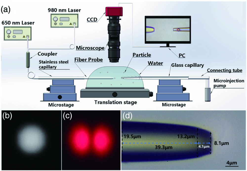
Fiber probes are fabricated using commercial single-mode fibers (Model: CS980-125-16/250, core diameter: 4.7 µm, cladding diameter: 125 µm; YOFC) by flame heating techniques[29]. The buffer layer and polymer jacket of the fibers are first stripped by using a fiber stripper. The stripped length of the fiber is 5 cm. To prevent it from breaking and warping, the fibers are wrapped with stainless steel capillaries (outer diameter: 0.5 mm, wall thickness: 0.1 mm, length: 100 mm). The fiber is heated for about 30 s to reach the melting point and then drawn at an initial speed of about 1.5 mm/s. The fiber diameter was reduced from 125 µm to 19.5 µm over a length of 5.27 mm. Then, it was sped up and drawn at a speed of about 16 mm/s. The fiber broke into a plane with a diameter of 8.1 µm. Finally, the fiber probe is completed by gently wiping the fiber tip with an alcohol-impregnated cotton towel.
Microcavities are made by heating and drawing glass capillaries and then placing microspheres in them. First, they are sealed by heating the ends of the glass capillary tubes (inner diameter: 0.1 mm, wall thickness: 0.1 mm, length: 100 mm). Then, heating was applied for about 12 s, followed by drawing at a rate of about 1.2 mm/s. The capillary diameter was reduced from 0.3 mm to 6.7 µm over a length of 7.86 mm. At this time, the heating and stretching of the capillary are stopped. The capillary is stretched at a speed of about 10 mm/s after the capillary has cooled for about 5 s. The end face of the capillary tube forms a hollow-core microtubule with an outer diameter of 6.7 µm and an inner diameter of 4.2 µm. Finally, polystyrene microspheres with a diameter of 6 µm are placed in the capillary to complete the microcavity.
The experimental setup is shown in Fig. 1(a). We realize the coupling of the 980 nm and 650 nm laser sources by using a
![]()
Figure 1.(a) Schematic of the experimental setup. (b) Image of far-field light intensity distribution of the excited LP01 mode beam. (c) Image of far-field light intensity distribution of the excited LP11 mode beam. (d) Optical micrographic image of flat-facet fiber probe.
The normalized frequency
![]()
Figure 2.Tapered fiber probe traps particles in the experiment. (a) Particle trapping was performed using an LP11 mode beam excited by a 650 nm laser source. (b) Particle trapping was performed using an LP01 mode beam excited by a 980 nm laser source. (The scale bars in the figure are all 4 µm.)
We established a simulation model through finite element analysis. The total light force
We use the wave optics module (electromagnetic waves, frequency domain) and perfectly matched layer boundary conditions to perform simulations in commercial finite element simulation software. The refractive indices of fiber, particle, and water are set to 1.45, 1.45, and 1.33, respectively. The particle diameter is set to 2 µm. The wavelengths are set to 650 nm and 980 nm, respectively. The input power is set to 1 W/m. The
![]()
Figure 3.(a)–(d) LP11 mode beam excited by a 650 nm laser passes through the electric field of the flat-facet fiber probe, details of the electric field distribution, applying a force on the particle in the x axis and a force on the particle along the y-axis direction. (e)–(h) LP01 mode beam excited by a 980 nm laser passes through the electric field of the flat-facet fiber probe, details of the electric field distribution, applying a force on the particle in the x axis and a force on the particle along the y-axis direction.
The power of the
3. Experimental Results and Discussions
Only the laser source with a wavelength of 650 nm was turned on, and the fiber probe output power was 5.33 mW. Silica particles with a diameter of 2 µm achieve non-contact trapping at a distance of about 2.7 µm from the fiber tip. By manipulating the fiber optic probe, the trapped particles can move about 42.36 µm along the
![]()
Figure 4.Manipulation of particles in the x–y plane. (The scale bars in the figure are all 4 µm.)
When
![]()
Figure 5.(a) Trajectory of particles being emitted when the 650 nm and 980 nm laser sources are turned on simultaneously. (The scale bars in the figure are all 4 µm.) (b) The horizontal position of the particle as a function of time.
The particles will not achieve trapping, only emission, when only the 980 nm laser source is turned on. When
![]()
Figure 6.(a) Particle emission trajectory when only the 980 nm laser source is turned on. (The scale bars in the figure are all 4 µm.) (b) The horizontal position of the particle as a function of time.
Based on the fact that we can achieve not only particle manipulation but also particle emission, we achieve particle transport. We show two of the processes of particle transport. The first transport process is shown in Fig. 7 (the microcavity is at the position of 35.6 µm in the
![]()
Figure 7.First transport process of the particle. (The scale bars in the figure are all 4 µm.)
The second process is shown in Fig. 8 (the microcavity is at the position of 44.3 µm in the
![]()
Figure 8.Second transport process of the particles. (The scale bars in the figure are all 4 µm.)
4. Conclusions
In this paper, we design and demonstrate a multifunctional single-fiber optical tweezer. It enables non-contact trapping and long-distance transport of particles. The structure uses a 650 nm laser source and a 980 nm laser source to generate the
References
[1] Y. Li, Y. Hu. Optical trapping and controllable targeted delivery of nanoparticles by a nanofiber ring. Appl. Phys. B, 124, 216(2018).
[2] X. Liu, Y. Wu, X. Xu, Y. Li, Y. Zhang, B. Li. Bidirectional transport of nanoparticles and cells with a bio-conveyor belt. Small, 15, 1905209(2019).
[3] J. El-Ali, P. K. Sorger, K. F. Jensen. Cells on chips. Nature, 442, 403(2006).
[4] S. Nagrath, L. V. Sequist, S. Maheswaran, D. W. Bell, D. Irimia, L. Ulkus, M. R. Smith, E. L. Kwak, S. Digumarthy, A. Muzikansky. Isolation of rare circulating tumour cells in cancer patients by microchip technology. Nature, 450, 1235(2007).
[5] P. S. Dittrich, K. Tachikawa, A. Manz. Micro total analysis systems. Latest advancements and trends. Anal. Chem., 78, 3887(2006).
[6] X. Fan, I. M. White. Optofluidic microsystems for chemical and biological analysis. Nat. Photonics, 5, 591(2011).
[7] N. Pamme, C. Wilhelm. Continuous sorting of magnetic cells via on-chip free-flow magnetophoresis. Lab Chip, 6, 974(2006).
[8] P. Puri, V. Kumar, S. U. Belgamwar, N. N. Sharma. Microfluidic device for cell trapping with carbon electrodes using dielectrophoresis. Biomed. Microdevices, 20, 102(2018).
[9] T. Jian, P. Rong, J. Ding. The regulation of stem cell differentiation by cell-cell contact on micropatterned material surfaces. Biomaterials, 31, 2470(2009).
[10] L. B. Yuan, Z. H. Liu, J. Yang, C. Y. Guan. Twin-core fiber optical tweezers. Opt. Express, 16, 4559(2008).
[11] Y. Li, H. Xin, X. Liu, B. Li. Non-contact intracellular binding of chloroplasts in vivo. Sci. Rep., 5, 10925(2015).
[12] Z. Liu, C. Guo, J. Yang, L. Yuan. Tapered fiber optical tweezers for microscopic particle trapping: fabrication and application. Opt. Express, 14, 12510(2006).
[13] R. Taylor, C. Hnatovsky. Particle trapping in 3-D using a single fiber probe with an annular light distribution. Opt. Express, 11, 2775(2003).
[14] Y. Zhang, H. Lei, B. Li. Refractive-index-based sorting of colloidal particles using a subwavelength optical fiber in a static fluid. APEX, 6, 072001(2013).
[15] H. Lei, C. Xu, Y. Zhang, B. Li. Bidirectional optical transportation and controllable positioning of nanoparticles using an optical nanofiber. Nanoscale, 4, 6707(2012).
[16] H. Lei, Y. Zhang, X. Li, B. Li. Photophoretic assembly and migration of dielectric particles and Escherichia coli in liquids using a subwavelength diameter optical fiber. Lab Chip, 11, 2241(2011).
[17] Z. Yu, Z. Liu, J. Yang, L. Yuan. Four-core optical fiber micro-hand. J. Light. Technol., 30, 1487(2012).
[18] Y. Zhang, Z. Liu, J. Yang, L. Yuan. An annular core single fiber tweezers. Sens. Lett., 10, 1374(2012).
[19] C. Liberale, P. Minzioni, F. Bragheri, F. D. Angelis, E. D. Fabrizio, I. Cristiani. Miniaturized all-fibre probe for three-dimensional optical trapping and manipulation. Nat. Photonics, 1, 723(2007).
[20] A. Kotnala, Y. Zheng. Opto-thermophoretic fiber tweezers. Nanophotonics, 8, 475(2019).
[21] Z. Li, J. Yang, S. Liu, X. Jiang, H. Wang, X. Hu, S. Xue, S. He, X. Xing. High throughput trapping and arrangement of biological cells using self-assembled optical tweezer. Opt. Express, 26, 34665(2018).
[22] B. J. Black, S. K. Mohanty. Fiber-optic spanner. Opt. Lett., 37, 5030(2012).
[23] Y. Zhang, Y. Zhou, X. Tang, Z. Wang, Y. Zhang, Z. Liu, J. Zhang, J. Yang, L. Yuan. Mode division multiplexing for multiple particles noncontact simultaneous trap. Opt. Lett., 46, 3017(2021).
[24] E. Zhao, Z. Liu, Y. Zhang, Y. Zhang, J. Yang, L. Yuan. A mode-division-multiplexing single fiber optical tweezers. Proc. SPIE, 9655, 96551D(2015).
[25] Z. H. Liu, P. B. Liang, Y. Zhang, J. J. Lei, Y. X. Zhang, J. Yang, L. B. Yuan. A micro-particle launching apparatus based on mode-division-multiplexing technology. Opt. Commun., 342, 30(2015).
[26] Z. Liu, P. Liang, Y. Zhang, Y. Zhang, E. Zhao, J. Yang, L. Yuan. Micro particle launcher/cleaner based on optical trapping technology. Opt. Express, 23, 8650(2015).
[27] R. Zeltner, D. S. Bykov, S. Xie, T. G. Euser, P. S. J. Russell. Fluorescence-based remote irradiation sensor in liquid-filled hollow-core photonic crystal fiber. Appl. Phys. Lett., 108, 231107(2016).
[28] H. Deng, Y. Zhang, T. Yuan, X. Zhang, Y. Zhang, Z. Liu, L. Yuan. Fiber-based optical gun for particle shooting. ACS Photonics, 4, 642(2017).
[29] H. Xin, Q. Liu, B. Li. Non-contact fiber-optical trapping of motile bacteria: dynamics observation and energy estimation. Sci. Rep., 4, 6576(2014).
[30] B. S. Schmidt, A. Yang, D. Erickson, M. Lipson. Optofluidic trapping and transport on solid core waveguides within a microfluidic device. Opt. Express, 15, 14322(2007).
[31] Z. Liu, L. Wang, P. Liang, Y. Zhang, J. Yang, L. Yuan. Mode division multiplexing technology for single-fiber optical trapping axial-position adjustment. Opt. Lett., 38, 2617(2013).


Set citation alerts for the article
Please enter your email address

© Copyright 2018-2021 | Chinese Laser Press. All Rights Reserved 沪ICP备15018463号-20