Abstract
A 1550 nm all-fiber pulsed laser Doppler vibrometer (LDV) based on time-domain chopping techniques is developed to overcome demodulation failures caused by multipath interference. The system adopts an adjustable configuration on pulse duration and pulse repetition frequency according to the distance. An experiment is carried out at a 25 m standoff with pulse duration of 80 ns, single pulse energy of 0.4 nJ, and pulse repetition frequency of 1 MHz. A waveform and spectrogram of the demodulated voice show that the pulsed LDV system has a good performance in long-range voice listening.Laser Doppler vibrometer (LDV) systems have played a great role in many industrial and military applications such as mine detection[1], structure health monitoring[2], and acoustic hearing[3], where the aim is to determine the vibration characteristics of an inaccessible target. It also presents possible applications in dynamic testing of mechanics, on-line quality control, as well as biomedicine fields[4]. Throughout the history of LDV, self-mixing technology[5], heterodyne technology[6], and linear frequency modulation (LFM) technology[7,8] are applied successively to improve the performance of LDV. But, two key issues, speckle and cochannel interference[9], have existed and plagued academic circles for so long. Speckle is presented as a random intensity fluctuation with a high-contrast pattern of bright and dark regions. Cochannel interference, which is also called three-wave interference by Leonid Yarovoi[10] and multipath interference by Georg Siegmund[11], occurs when the intensity of light scattered from two or more surfaces in the optical transmission path matches that from the vibrating surface. Typically, in-fiber-coupled LDV internal scattering of the fiber material or of the fiber end surfaces can cause significant reflected power[11]. It corrupts the information of the Doppler signal and even causes the failure of demodulation. In this Letter, to overcome the impact of cochannel interference, we propose a 1550 nm pulsed all-fiber LDV prototype based on time-domain chopping (TDC) techniques to separate and to cut off the interference of the cochannel signal in the time domain.
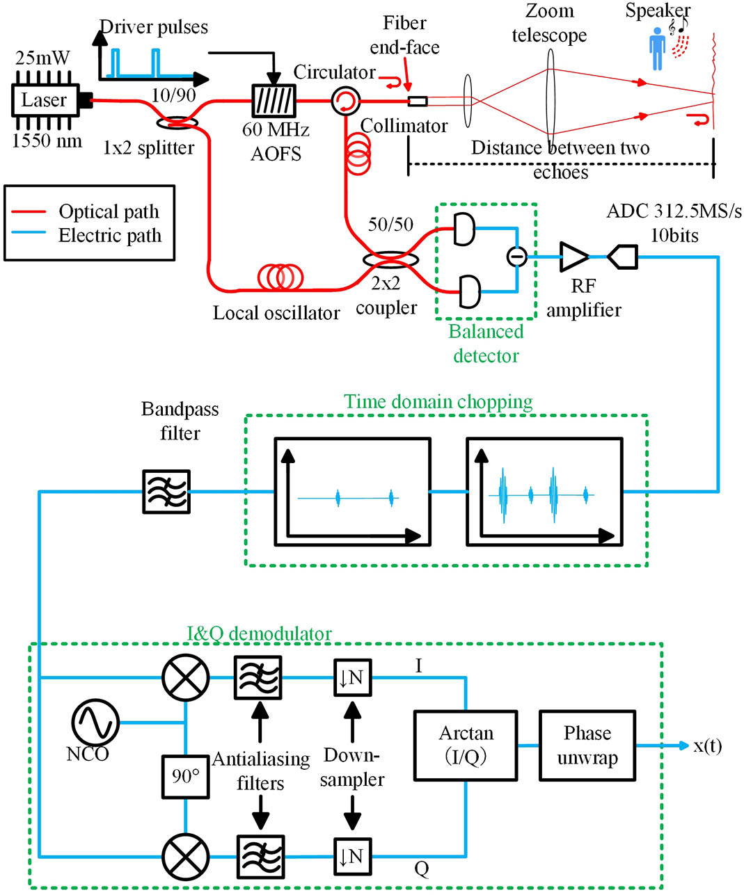
The schematic configuration of the all-fiber pulsed LDV system is depicted in Fig. 1. The LDV system is composed of the optical unit and the electrical unit. In the optical unit, an eye-safe, single-mode, continuous-wave (CW) fiber laser with an output power of 25 mW and the linewidth of less than 10 kHz [full width at half-maximum (FWHM)] is divided into two paths by a beam splitter (ratio 10/90). Ten percent of the laser power acts as the local oscillator (LO), and the rest of the power is utilized in the transmitted path. An acoustic-optic fiber shifter (AOFS), which is driven by pulse train voltage, is equipped in the transmitted path in order to generate a pulsed laser mode, as well as to discriminate motion direction. Frequency-shifted by 60 MHz in an AOFS and passing through an optical circulator and a FiberPort collimator, the transmitted laser pulse is focused onto an optical rough surface, which is vibrated by the sound of a loudspeaker. Within a pulse period, the first group of echoes is reflected from the fiber end-face, and the second one is back-reflected from the vibrating surface. They both mix with the continuous LO beam in a coupler. The mixed light splits into two approximately equal portions to feed into a balanced amplified photodetector, which utilizes two well-matched, pigtailed avalanche photodiodes (APDs) and an ultra-low noise, ultra-low distortion transimpedance amplifier to suppress the common-mode noise. Subsequently, the heterodyne voltage results from the difference of the two optical input signals. In the electrical unit, the heterodyne signal is amplified to suit the range of the analog-to-digital converter’s (ADC) peak-to-peak value. After amplification, the RF heterodyne signal from the balanced photodetector is sampled at 312.5 MS/s by a 10 bit ADC (NI-PXIe 5162). Offline processing is adopted to demonstrate the principle of the pulsed LDV system. Meanwhile, a real-time signal processing based on a field programmable gate array (FPGA) is being developed. The sampled intermediate frequency (IF) signal is processed by the TDC algorithm. An in-phase and quadrature (I&Q) demodulator is designed to down-convert the IF signal into a baseband signal with the frequency of a numerically controlled oscillator (NCO) set to match the IF. After passing through an antialiasing filter and a down-sampler, the baseband signal completes the phase arctangent algorithm. A phase unwrapping algorithm follows behind the result of the phase arctangent algorithm to correct the phase wrapping. The displacement of a vibrating surface is extracted according to . The velocity of the vibrating surface is simply determined by calculating the derivative of the displacement.

Figure 1.Schematic diagram of the all-fiber pulsed LDV system.
The signal-to-noise ratio (SNR) is the key parameter to evaluate the performance of the LDV system. Typically, the SNR of the free space system is determined by the configuration of the LDV system, the transmission loss, and the reflective properties of the target. The configuration of the system is graphically detailed in Fig. 1. The theoretical key transmission loss in the system is listed in Table 1. Additionally, a power measurement test is implemented, and the power of the key node in the optic circuit is graphically listed in Table 1 as well. But, in an all-fiber-coupled system, the back-reflection from the fiber end-face is inevitable. The SNR calculated in a continuous mode is no longer suitable for characterizing the ability of sensing. Therefore, in pulsed mode, after the back-reflected echoes are removed (which is called the TDC technique), the calculated SNR is really meaningful.
Sign up for Chinese Optics Letters TOC. Get the latest issue of Chinese Optics Letters delivered right to you!Sign up now
| | Parameter | Value |
|---|
| Theoretical value | AOFS insertion loss | 3 dB |
| Circulator insertion loss | 1 dB |
| Collimator with anti-reflective coating | 0.2% reflectivity |
| Zoom telescope with anti-reflective coating | 0.2% reflectivity |
| 2×2 coupler insertion loss | ≤3.4 dB |
| 1×2 splitter insertion loss | ≤0.8 dB/≤10.5 dB |
| Measurement test |  |
Table 1. Transmission Loss of the Optical Path in the System
The principle of the TDC signal process method is detailed in Fig. 2. In Fig. 2(a), within every pulse period, the first group of echoes that comes from the end-face of the fiber is at a stable height above the shot noise floor. It contains no information about the vibrating surface and can impair the demodulation process, while the second group of echoes scattered by the vibrating surface has a very small amplitude or can even be submerged in the noise. The information of the vibration characteristics buried in these echoes is exactly what we wanted. The key idea of the TDC is to cut off the whole signal except for the echoes from the vibrating surface. In order to find the echoes buried in the noise, a matched filter process is carried out. As shown in Fig. 2(b), the time-of-flight delay can be calculated by subtracting the positions of peaks of echoes in the matched filtered signal. Threshold detection is completed to find the peak position of the first group of echoes. The position of the informative echoes is estimated by adding the time-of-flight delay to the peak position of the first group of echoes. Therefore, a time-chopped signal is obtained in Fig. 2(c).
Figure 2.Principle of TDC signal process method: (a) heterodyne mixing signal, (b) matched filtered signal, and (c) time-chopped signal.
An experiment is carried out to evaluate the performance of the pulsed system. The experiment layout is shown in Fig. 3. A polyvinyl chloride (PVC) file folder, which has a typical rough surface, is selected as the vibrating surface for its good representation of the objects encountered in everyday life. It is placed 25 m away from the LDV and vibrated by a nearby loudspeaker. A decibel (dB) meter indicates that the averaged voice power of the speaker is about 65 dB. The pulse width and pulse repetition frequency (PRF) can be adjusted according to the distance. In order to avoid overlapping of echoes, a pulse width of 80 ns and a PRF of 1 MHz are selected. Because the AOFS and the circulator both have a 3 dB attenuation in power, the output power in a CW mode is approximately 5 mW. Therefore, every pulse has an energy of 0.4 nJ. Since the frequency of the human voice varies from 300 Hz to 3 kHz, the bandwidth of the spectrogram is set to be 3 kHz. The waveform and spectrogram of the voice demodulated from the file folder are graphed in Fig. 4(b). As a comparison, the voice recorded by a microphone is illustrated in Fig. 4(a). The pictures show that although the voice demodulated has a high-frequency loss compared to the one that was recorded by the microphone, it has a comprehensive understanding and good clarity overall.
Figure 3.Voice acquisition experiment layout.
Figure 4.Waveform and spectrum of (a) voice recorded by a microphone and (b) voice demodulated from a file folder at a 25 m standoff.
In conclusion, a compact all-fiber pulsed LDV system based on the TDC technique for long-range voice listening is developed. The advantage of the TDC technique is to solve the inherent problem of the LDV system due to cochannel interference. The experimental results indicate that the all-fiber pulsed LDV system has a good performance for long-range voice listening at a 25 m standoff with a pulse energy of 0.4 nJ and a PRF of 1 MHz. Actually, applying a fiber amplifier [e.g., erbium-doped fiber amplifier (EDFA)], suppressing the laser noise, and reducing the system loss are all ways to improve the SNR of the system.
References
[1] V. Aranchuk, A. Lal, C. Hess, J. M. Sabatier. Opt. Eng., 45, 104302(2006).
[2] P. Castellini, N. Paone, E. P. Tomasini. Opt. Lasers Eng., 25, 227(1996).
[3] J. H. Shang, Y. He, D. Liu, W. B. Chen. Lasers & Electro-Optics & the Pacific Rim Conference on Lasers and Electro-Optics, 389(2009).
[4] S. J. Rothberg, M. S. Allen, P. Castellini, D. Di Maio, J. J. J. Dirckx, D. J. Ewins, B. J. Halkon, P. Muyshondt, N. Paone, T. Ryan, H. Steger, E. P. Tomasini, S. Vanlanduit, J. F. Vignola. Opt. Lasers Eng., 99, 11(2017).
[5] S. Donati, M. Norgia. IEEE J. Sel. Top. Quant. Electron., 20, 6900108(2014).
[6] J. R. Rzasa, K. Cho, C. C. Davis. Appl. Opt., 54, 6230(2015).
[7] P. Feneyrou, L. Leviandier, J. Minet, G. Pillet, A. Martin, D. Dolfi, J. P. Schlotterbeck, P. Rondeau, X. Lacondemine, A. Rieu, T. Midavaine. Appl. Opt., 56, 9663(2017).
[8] P. Feneyrou, L. Leviandier, J. Minet, G. Pillet, A. Martin, D. Dolfi, J. P. Schlotterbeck, P. Rondeau, X. Lacondemine, A. Rieu, T. Midavaine. Appl. Opt., 56, 9676(2017).
[9] C. A. Hill, M. Harris, K. D. Ridley, E. Jakeman, P. Lutzmann. Appl. Opt., 42, 1091(2003).
[10] L. Yarovoi, G. Siegmund. Meas. Sci. Technol., 15, 2150(2004).
[11] G. Siegmund, 7098, 70980Y(2008).