
Zhimin Wang, Rui Tian, Jingchao Qi, Peitao Li, Qiang Wei. Structural Design and Optical Performance of Inverted Trapezoidal Cavity Receiver[J]. Acta Optica Sinica, 2017, 37(12): 1222003
- Acta Optica Sinica
- Vol. 37, Issue 12, 1222003 (2017)
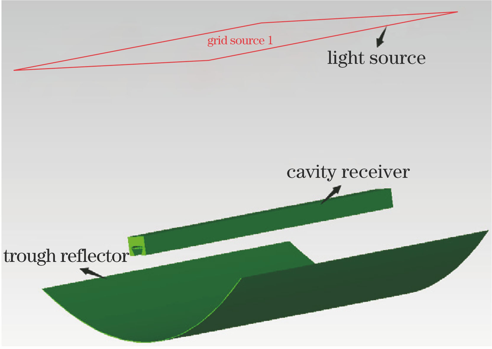
Fig. 1. Schematic of trough reflector-cavity receiver thermal collection system
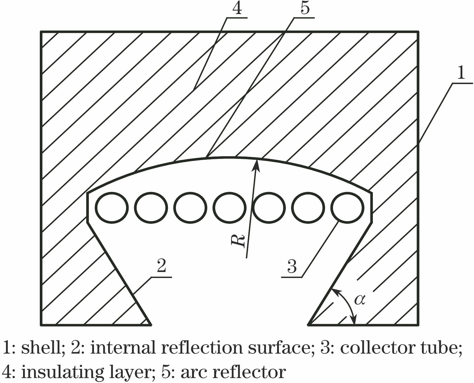
Fig. 2. Profile structure of the cavity receiver
Fig. 3. Ray path diagram of the heat collection system
Fig. 4. Influence of opening angle α on optical efficiency
Fig. 5. Influence of the radius of arc reflector on optical efficiency
Fig. 6. Influence of different parameters of cavity structure on optical efficiency
Fig. 7. Energy flux distribution of collector tube wall for different cavity structures
Fig. 8. Energy flux standard deviation of collector tube wall for different cavity structures
Fig. 9. Maximum Nu for different collector tubes
Fig. 10. Influence of vertical deviation on optical performance
Fig. 11. Influence of horizontal deviation on optical performance
Fig. 12. (a) Flow chart and (b) physical photo of the test system
Fig. 13. Normalized thermal collection efficiency
|
Table 1. Parameters of the parabolic trough concentrator
|
Table 2. Structure parameters of the cavity receiver

Set citation alerts for the article
Please enter your email address
© Copyright 2018-2021 | Chinese Laser Press. All Rights Reserved 沪ICP备15018463号-20