• Advanced Photonics
  • Vol. 3, Issue 1, 014002 (2021)
Dong Mao1, Yang Zheng1, Chao Zeng1, Hua Lu1, Cong Wang2, Han Zhang2, Wending Zhang1、*, Ting Mei1, and Jianlin Zhao1
Author Affiliations
  • 1Northwestern Polytechnical University, School of Physical Science and Technology, MOE Key Laboratory of Material Physics and Chemistry Under Extraordinary Conditions, and Shaanxi Key Laboratory of Optical Information Technology, Xi’an, China
  • 2Shenzhen University, Collaborative Innovation Centre for Optoelectronic Science and Technology, Key Laboratory of Optoelectronic Devices and Systems of Ministry of Education and Guangdong Province, Shenzhen, China
  • show less
    DOI: 10.1117/1.AP.3.1.014002 Cite this Article Set citation alerts
    Dong Mao, Yang Zheng, Chao Zeng, Hua Lu, Cong Wang, Han Zhang, Wending Zhang, Ting Mei, Jianlin Zhao. Generation of polarization and phase singular beams in fibers and fiber lasers[J]. Advanced Photonics, 2021, 3(1): 014002 Copy Citation Text show less
    Polarization distribution of (a) natural, unpolarized light, (b) linearly polarized beam, (c) RPB, (d) APB, and (e) hybridly polarized beam.
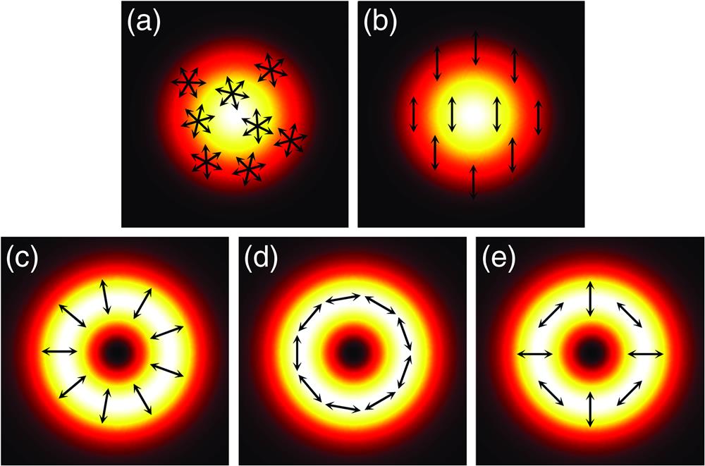
    Fig. 1. Polarization distribution of (a) natural, unpolarized light, (b) linearly polarized beam, (c) RPB, (d) APB, and (e) hybridly polarized beam.
    Phase evolution of (a) VB, (b) plane wave, and (c) spherical wave.
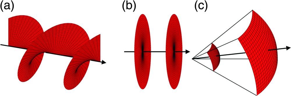
    Fig. 2. Phase evolution of (a) VB, (b) plane wave, and (c) spherical wave.
    Mode distributions of TMF under (a) scalar approximation and (b) corresponding groups of the vector modes. Adapted with permission from Ref. 80 © OSA Publishing.
    Fig. 3. Mode distributions of TMF under (a) scalar approximation and (b) corresponding groups of the vector modes. Adapted with permission from Ref. 80 © OSA Publishing.
    (a) Flow diagram and (b) experimental setup for generating CVBs based on an acoustically induced LPFG. SMF, single-mode fiber; EDFA, erbium-doped fiber amplifier; PC, polarization controller; TMF, two-mode fiber; MS, mode stripper; MO, micro-objective; GT, Glan–Taylor prism polarizer; CCD, charge coupled device. (c) Intensity patterns of (c1), (c3), (c5) RPB and (c2), (c4), (c6) APB at (c1), (c2) 633 nm, (c3), (c4) 532 nm, and (c5), (c6) 1550 nm before and after passing a polarizer. Adapted with permission from Ref. 80 © OSA Publishing.
    Fig. 4. (a) Flow diagram and (b) experimental setup for generating CVBs based on an acoustically induced LPFG. SMF, single-mode fiber; EDFA, erbium-doped fiber amplifier; PC, polarization controller; TMF, two-mode fiber; MS, mode stripper; MO, micro-objective; GT, Glan–Taylor prism polarizer; CCD, charge coupled device. (c) Intensity patterns of (c1), (c3), (c5) RPB and (c2), (c4), (c6) APB at (c1), (c2) 633 nm, (c3), (c4) 532 nm, and (c5), (c6) 1550 nm before and after passing a polarizer. Adapted with permission from Ref. 80 © OSA Publishing.
    Mode-selective coupler based on tapered SMF and TMF.
    Fig. 5. Mode-selective coupler based on tapered SMF and TMF.
    (a) Configuration of the all-TMF laser for LP11 mode oscillation. TM-EDF, two-mode erbium-doped fiber; PC, polarization controller; OSA, optical spectrum analyzer; CCD, charge coupled device; MSC, mode-selective coupler; WDM, wavelength division multiplexer. (b) Spectrum of the TMF laser; the inset shows the near-field pattern of the generated LP11 mode. (c) The relationship between the pump and output powers. Adapted with permission from Ref. 101 © OSA Publishing.
    Fig. 6. (a) Configuration of the all-TMF laser for LP11 mode oscillation. TM-EDF, two-mode erbium-doped fiber; PC, polarization controller; OSA, optical spectrum analyzer; CCD, charge coupled device; MSC, mode-selective coupler; WDM, wavelength division multiplexer. (b) Spectrum of the TMF laser; the inset shows the near-field pattern of the generated LP11 mode. (c) The relationship between the pump and output powers. Adapted with permission from Ref. 101 © OSA Publishing.
    (a) Diagram of the offset-spliced SMF and TMF. Calculated coupling efficiency of the fundamental mode to (b) TM01 mode and (c) TE01 mode versus mismatch distances ΔR. The polarization of the fundamental mode is (b) parallel and (c) perpendicular to the mismatch direction y, respectively. The insets show the calculated normalized intensities and polarization distributions of the TM01 and TE01 modes, respectively. (d) Measured images of the SMF and TMF before and after splicing. Adapted with permission from Ref. 105 © AIP Publishing.
    Fig. 7. (a) Diagram of the offset-spliced SMF and TMF. Calculated coupling efficiency of the fundamental mode to (b) TM01 mode and (c) TE01 mode versus mismatch distances ΔR. The polarization of the fundamental mode is (b) parallel and (c) perpendicular to the mismatch direction y, respectively. The insets show the calculated normalized intensities and polarization distributions of the TM01 and TE01 modes, respectively. (d) Measured images of the SMF and TMF before and after splicing. Adapted with permission from Ref. 105 © AIP Publishing.
    (a) Reflection spectrum of TMFBG and SMFBG. (b) Intensity distribution of radially polarized laser beam before and after passing through a linear polarizer with the transmission axis orientation denoted by arrows. Adapted with permission from Ref. 108 © OSA Publishing.
    Fig. 8. (a) Reflection spectrum of TMFBG and SMFBG. (b) Intensity distribution of radially polarized laser beam before and after passing through a linear polarizer with the transmission axis orientation denoted by arrows. Adapted with permission from Ref. 108 © OSA Publishing.
    Q-switched and mode-locked cylindrical vector beam lasers. Mode-locked (a) RPB and (b) APB before and after passing through a polarizer. (c) Optical spectra and (d) pulse trains of Q-switched and mode-locked cylindrical vector beam lasers. (e) Evolution of Q-switched cylindrical vector beam lasers. (f) Autocorrelation traces of mode-locked cylindrical vector beam lasers. Adapted with permission from Ref. 105 © AIP Publishing.
    Fig. 9. Q-switched and mode-locked cylindrical vector beam lasers. Mode-locked (a) RPB and (b) APB before and after passing through a polarizer. (c) Optical spectra and (d) pulse trains of Q-switched and mode-locked cylindrical vector beam lasers. (e) Evolution of Q-switched cylindrical vector beam lasers. (f) Autocorrelation traces of mode-locked cylindrical vector beam lasers. Adapted with permission from Ref. 105 © AIP Publishing.
    Formation mechanism of VBs in TMF. (a1)–(a4) mode distribution of TM01, HE21even, HE21odd, and TE01 modes. Mode distribution, phase, and polarization of (b1)–(b3), (c1)–(c3) circularly polarized VBs and (d1)–(e3), (e1)–(e3) linearly polarized VBs.
    Fig. 10. Formation mechanism of VBs in TMF. (a1)–(a4) mode distribution of TM01, HE21even, HE21odd, and TE01 modes. Mode distribution, phase, and polarization of (b1)–(b3), (c1)–(c3) circularly polarized VBs and (d1)–(e3), (e1)–(e3) linearly polarized VBs.
    Generation of VBs based on an acoustically-induced LPFG. (a) Experiment setup. EDFA, erbium-doped fiber amplifier; SMF, single-mode fiber; PC, polarization controller; MS, mode stripper; TMF, two-mode fiber; MO, micro-objective; NPBS, nonpolarizing beam splitter; CCD, charge coupled device. (b) VBs and coaxial interference patterns at wavelengths of 1540, 1545, 1550, 1555, and 1560 nm. Adapted with permission from Ref. 118 © OSA Publishing.
    Fig. 11. Generation of VBs based on an acoustically-induced LPFG. (a) Experiment setup. EDFA, erbium-doped fiber amplifier; SMF, single-mode fiber; PC, polarization controller; MS, mode stripper; TMF, two-mode fiber; MO, micro-objective; NPBS, nonpolarizing beam splitter; CCD, charge coupled device. (b) VBs and coaxial interference patterns at wavelengths of 1540, 1545, 1550, 1555, and 1560 nm. Adapted with permission from Ref. 118 © OSA Publishing.
    (a) Principle of the VB converter based on a mechanical LPFG. Intensity profiles of (b1) −1-order and (b3) +1-order VB. Coaxial interference patterns of (b2) −1-order and (b4) +1-order VB with a Gaussian beam. Adapted with permission from Ref. 120 © OSA Publishing.
    Fig. 12. (a) Principle of the VB converter based on a mechanical LPFG. Intensity profiles of (b1) 1-order and (b3) +1-order VB. Coaxial interference patterns of (b2) 1-order and (b4) +1-order VB with a Gaussian beam. Adapted with permission from Ref. 120 © OSA Publishing.
    (a) Mode coupling and output elements are the LPFG and fiber mirror, SMF-TMF taper and TMFBG, and LPFG and TMFBG for schemes 1, 2, and 3, respectively. (b) Intensity distributions and interference patterns, (c) optical spectra, and (d) autocorrelation traces of mode-locked vortex lasers. l, topological charge. Adapted with permission from Ref. 130 © AIP Publishing.
    Fig. 13. (a) Mode coupling and output elements are the LPFG and fiber mirror, SMF-TMF taper and TMFBG, and LPFG and TMFBG for schemes 1, 2, and 3, respectively. (b) Intensity distributions and interference patterns, (c) optical spectra, and (d) autocorrelation traces of mode-locked vortex lasers. l, topological charge. Adapted with permission from Ref. 130 © AIP Publishing.
    Coupling deviceOutput deviceWavelength (nm)Mode purityOutput power (mW)Pulse durationGeneration systemSupplementary informationRef.
    LPFGTMF1450/162099.8%//Ring-shaped fiberMicrobend grating, period: 800  μm; insertion loss: 0.05%117
    LPFGTMF1550/633/53299.9%2.4/TMFAcoustically induced LPFG80
    LPFGTMF1529.1 to 1563.199%//TMFCO2-laser written LPFG85
    LPFGTMFBG1548.698%72/Linear cavity fiber laserCO2-laser written LPFG89
    Mode-selective couplerTMF1556.394%3.517 nsFigure-8 fiber laserInsertion loss 0.65 dB97
    Mode-selective couplerTMF156095%41.78 psSeeded ring fiber laser/101
    Mode-selective couplerTMF1532.5 and 1555.597%0.60.5/0.59 psRing fiber laserInsertion loss 0.65 dB98
    Symmetric TMF couplerTMF1564.491%12.552 psRing fiber laser/99
    Offset-spliced fiberTMF632.8Low//TMF/104
    Offset-spliced fiberTMFBG105394%3.2/Linear-cavity fiber laserContinuous wave106
    Offset-spliced fiberTMFBG1550/4.66958 nsRing fiber laserQ-switched pulse107
    Offset-spliced fiberTMFBG1550.5//6.87 psRing fiber laserMode-locked pulse, insertion loss: 3 dB105
    Offset-spliced fiberTMFBG1056.396%2.52.8 to 23 nsFigure-8 fiber laserRectangular pulse108
    Tapered fiberTMFBG1548.9/12 to 185.2 to 39.2 psRing fiber laserMode-locked pulse, insertion loss: 0.36 dB115
    Table 1. Generation systems and performances of CVBs using different schemes.
    Coupling deviceOutput elementWavelength (nm)Mode purityOutput power (mW)Pulse durationGeneration systemSupplementary informationRef.
    LPFGTMF1520 to 1570100%//TMFAcoustically induced LPFG84
    LPFGTMF1530 to 162597%//TMFMechanically induced LPFG120
    LPFGTMF152797%//Ring-shaped fiberMechanically induced LPFG82
    LPFGTMF1540 to 156095%//TMFAcoustically induced LPFG118
    LPFGLPFG156095%/0.384 psTMFAcoustically induced LPFG55
    LPFGTMF1548.6/1548.9/34.77/35.286.96/6.01 psFiber ring laserMechanically induced LPFG130
    LPFGFiber mirror1547.4/1547.5/8.9/6.990.90 to 5.28/0.84 to 5.28 psFiber ring laserMechanically induced LPFG130
    Helical LPFGHelical LPFG1550100%//TMF/121
    Helical LPFGHelical LPFG155090%//Four-mode fiberHelical LPFG inscribed by CO2 laser125
    Mode-selective couplerFMF1547.4/5.5OAM±1 273 fs; OAM±2 140 fsFiber ring laser/100
    Mode-selective couplerTMF155090%//TMF/127
    Tapered fiberTMFBG1547.4/1547.5/32.9/35.896.47/6.38 psFiber ring laser/130
    Vortex gratingTMF/95%//TMFVortex grating on fiber facet133
    Table 2. Generation systems and performances of VBs based on different schemes.
    Dong Mao, Yang Zheng, Chao Zeng, Hua Lu, Cong Wang, Han Zhang, Wending Zhang, Ting Mei, Jianlin Zhao. Generation of polarization and phase singular beams in fibers and fiber lasers[J]. Advanced Photonics, 2021, 3(1): 014002
    Download Citation