• Infrared and Laser Engineering
  • Vol. 50, Issue 6, 20200331 (2021)
Xinrui Xu1, Xiangxiang Meng1、2、*, Shichen Wu1, Jianlong Wang1, and Suping Bai3
Author Affiliations
  • 1Shandong Institute of Aerospace Electronics Technology, Yantai 264000, China
  • 2School of Opto-Electronic Information Science and Technology, Yantai University, Yantai 264005, China
  • 3School of Opto-Electronic Engineering, Changchun University of Science and Technology, Changchun 130022, China
  • show less
    DOI: 10.3788/IRLA20200331 Cite this Article
    Xinrui Xu, Xiangxiang Meng, Shichen Wu, Jianlong Wang, Suping Bai. Development of optical antenna for middle infrared laser communication terminal[J]. Infrared and Laser Engineering, 2021, 50(6): 20200331 Copy Citation Text show less
    Diagram of inverted structure of Kepler telescope
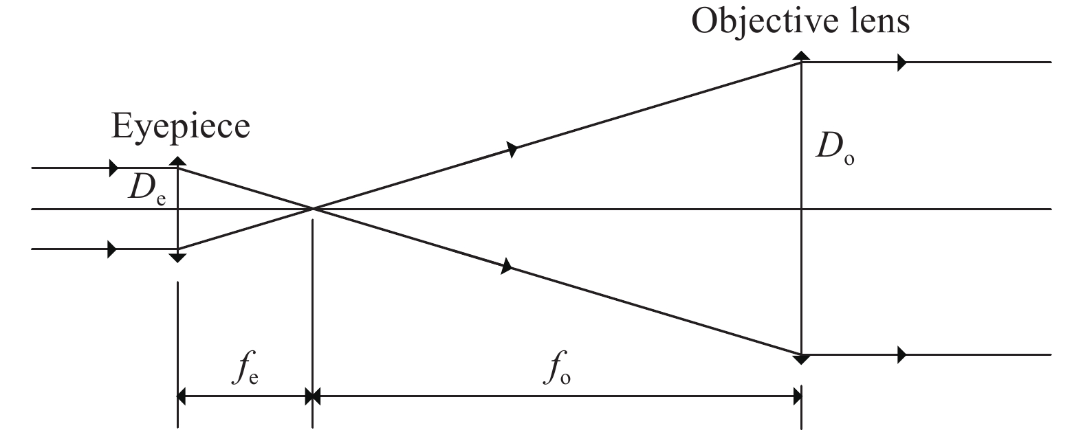
    Fig. 1. Diagram of inverted structure of Kepler telescope
    Optical path diagram of transmitting optical antenna objective lens
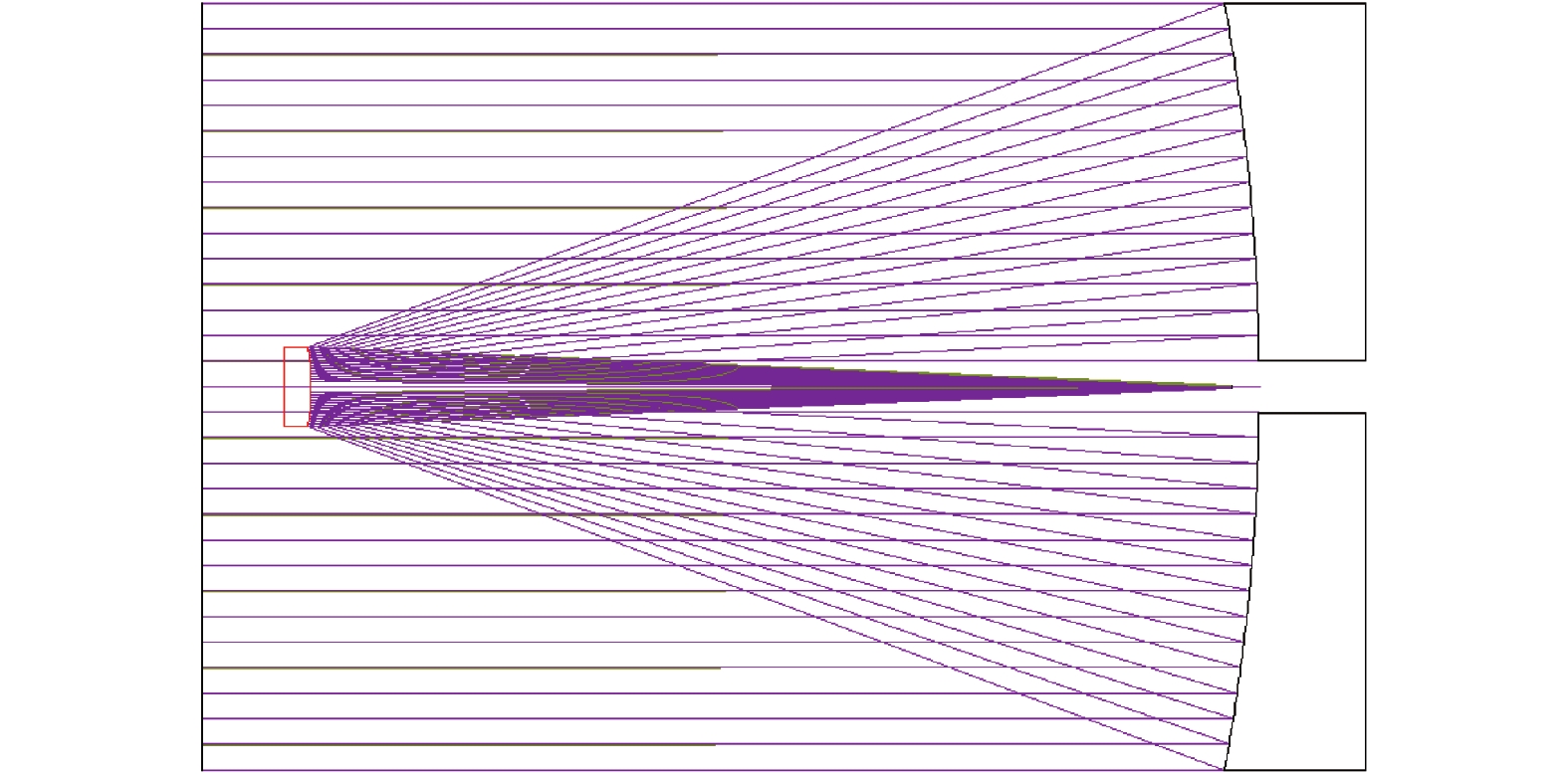
    Fig. 2. Optical path diagram of transmitting optical antenna objective lens
    Optical path diagram of transmitting optical antenna
    Fig. 3. Optical path diagram of transmitting optical antenna
    Design results of transmitting optical antenna. (a) MTF; (b) Diagram of wavefront aberration
    Fig. 4. Design results of transmitting optical antenna. (a) MTF; (b) Diagram of wavefront aberration
    Optical path diagram of receiving optical antenna
    Fig. 5. Optical path diagram of receiving optical antenna
    Receiving optical antenna design results. (a) MTF; (b) Diagram of wavefront aberration; (c) Diagram of spot
    Fig. 6. Receiving optical antenna design results. (a) MTF; (b) Diagram of wavefront aberration; (c) Diagram of spot
    Wavefront aberration with temperature
    Fig. 7. Wavefront aberration with temperature
    Transmitting optical antenna. (a) Diagram of structure design; (b) Diagram of physical object (without hood)
    Fig. 8. Transmitting optical antenna. (a) Diagram of structure design; (b) Diagram of physical object (without hood)
    Receiving optical antenna. (a) Diagram of structure design; (b) Diagram of physical object
    Fig. 9. Receiving optical antenna. (a) Diagram of structure design; (b) Diagram of physical object
    MTF testing of transmitting optical antenna. (a) Testing; (b) The measured MTF
    Fig. 10. MTF testing of transmitting optical antenna. (a) Testing; (b) The measured MTF
    Test results of receiving optical antenna wavefront aberration (test wavelength 632.8 nm)
    Fig. 11. Test results of receiving optical antenna wavefront aberration (test wavelength 632.8 nm)
    ParameterSpecificationNotes
    Communication transmitting power/dBm17.78Laser modulation power is 60 mW,Laser wavelength is 4.7 μm
    Transmitting antenna gain/dB85.51The emission aperture is 290 mm
    Transmitting antenna loss/dB−2.22Transmitting optical efficiency is 0.6
    Wavefront loss/dB−1.71Wavefront aberration RMS≤0.1λλ= 4.7 μm
    Space loss/dB−208.510 km
    Alignment adaptation loss/dB−0.01High alignment precision
    Atmospheric absorption/dB−3.62Atmospheric attenuation
    Receiving antenna gain/dB106.1The receiving aperture is 310 mm
    Receiving antenna loss/dB−2.22Receiving optical efficiency is 0.6
    Detector actual receiving power/dBm−9.48Actual arrival power to detector
    Detector receiving threshold/dBm−12BER=10−6,1 Gpbs
    Table 1. Calculation table of midde infrared laser communication link
    Xinrui Xu, Xiangxiang Meng, Shichen Wu, Jianlong Wang, Suping Bai. Development of optical antenna for middle infrared laser communication terminal[J]. Infrared and Laser Engineering, 2021, 50(6): 20200331
    Download Citation