
An Ye, Dingyuan Fu, Mingming Wu, Jiahao Guo, Tianze Sheng, Xiaolin Li, Shangqing Gong, Yueping Niu. SNR enhancement of magnetic fields measurement with the diamond NV center using a compound filter system[J]. Chinese Optics Letters, 2023, 21(11): 111201
- Chinese Optics Letters
- Vol. 21, Issue 11, 111201 (2023)
Abstract
1. Introduction
Nitrogen-vacancy (NV) centers are typical luminous point defects in diamond with the characterization of excellent spin properties[1]. The NV diamond has offered new possibilities to explore many intriguing quantum phenomena[2,3]. Meanwhile, the NV diamond has also been used as a tool for the sensing of the magnetic field[4,5], temperature[6], electric field[7], and pressure[8] with high spatial resolution and high sensitivity via optically detected magnetic resonance (ODMR). Recently, a quantum sensing platform employing the NV diamond was swiftly developed; in particular, the NV diamond-based magnetometry has gained increasing interest[9], which shows diversities of applications such as in the fields of single-neuron action[10], tumor tissues imaging[11], and geological samples[12].
However, the ODMR spectrum is always mixed with many kinds of noise, which will cause error judgement for the real signal. Typically, the techniques of optimizing NV diamond ODMR focus on signal amplitude enhancement[13-15]. For noise processing, a differential measurement is generally performed for the purpose of the reduction of laser-induced or microwave-induced noise[5,9,16]. Few efficient noise-specific treatments have been applied to optimize the NV diamond magnetometry. The introduction of the digital filter approaches into the NV diamond-based magnetic measurement will be beneficial to the signal processing due to the remarkable denoising effect.
There are many filter methods suitable for optical signal denoising, such as wavelet filter[17], Kalman filter[18], and Wiener filter[19]. The wavelet threshold denoising approach is a common wavelet filter. It decomposes the spectral signal into different wavelet coefficients, then removes the wavelet coefficients including noise with an appropriate threshold, and finally reconstructs the signal. As a denoising approach of high efficiency, the wavelet threshold denoising approach displays superiority in the convenient calculation process, low computational complexity, and obvious denoising effect[20]. Additionally, the adaptive filter is also an important tool in signal processing because it can automatically adjust the filter parameters to achieve the optimal filter effect in an unknown environment. Recently, the mixture of wavelet transform and adaptive filter has been applied in many applications, such as speech signals[21], active noise control[22], and electrocardiogram signals[23], and all of them have acquired notable achievements. However, few works have been published on the use of digital filters in the field of NV diamonds.
Sign up for Chinese Optics Letters TOC. Get the latest issue of Chinese Optics Letters delivered right to you!Sign up now
In this paper, we apply a compound filter system combining a wavelet transform-based adaptive filter and a wavelet denoising method to the NV diamond-based ODMR signal. Notably, it accomplishes significant performance improvement when processing a noisy signal, even without acquiring the statistical properties of any prior information. By evaluating the results of signal to noise ratio (SNR) enhancement[24], we compare the denoising effects of the filter system under different conditions. The parameters of the adaptive filter are also updated by making use of the SNR, in order to yield the optimal working points. Actually, when digital filters such as the wavelet transform or the adaptive filter are introduced into a field, they often make great improvements in it[25-27]. So, we attempt to explore a new possibility of improving NV-based signals. After comparing with other filters, we have found that the combination of wavelet denoising method combined time-frequency domains analysis and an adaptive filter with automatic parameter adjustment outperforms traditional filters. Such an NV-based magnetic measurement denoising technique combining a filter system may contribute to realizing the real-time weak magnetic field measurement with high resolution.
2. Methodology
2.1. Experimental setup and differential measurement
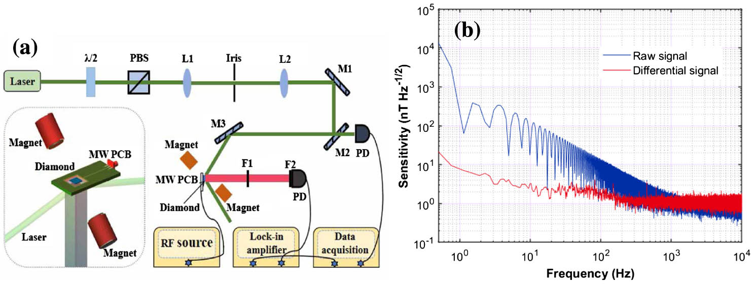
As shown in Fig. 1(a), an excitation beam at 532 nm is focused on a lightguide, where the diamond is located to illuminate NV centers. The microwave field created by a microwave generator (Keysight E8257D) and amplified by a power amplifier (Mini-Circuits ZHL-16W-43-S+) is delivered to the NV centers through a microwave printed circuit board with an antenna. The fluorescence emitted from NV centers is collected by a photodiode loaded with a long-pass filter and then transferred to a lock-in amplifier (Zurich Instruments HF2LI) to be demodulated. To perform the differential measurements, we monitor an additional laser signal by a second photodiode to record the laser power ripple. What is more, a pair of magnets is aligned to the corresponding NV axis to provide a bias magnetic field of about 70 G. A pair of Helmholtz coils is aligned with the same axis which generates magnetic field to be measured.
![]()
Figure 1.(a) Schematic of the experimental setup. The inset depicts the detailed section for ODMR. (b) The magnetic field sensitivity measured by continuous wave ODMR method. The blue and red lines show the sensitivity obtained from the direct outputs of measurements with and without the differential method.
The noise in measurements is greatly caused by the unstable intensity of the laser[9], thus causing the amplitude noise associated with the time domain in the NV-based fluorescence signal. In order to eliminate the impact of laser noise on real signals to the greatest extent, we subtract the time domain variation of the laser recorded by an extra photodiode from the collected fluorescent signal. Figure 1(b) presents the sensitivity of raw and differential signals. After the differential measurement, the signal sensitivity at low frequency is significantly improved, whereas further improved performance cannot be achieved at high frequency owing to the inevitable electronics noise. Therefore, we need to do more with the differential signal. To get a better denoised signal, the wavelet transform is considered because of its excellent performance in the signal processing with the laser involved[28,29].
2.2. Discrete wavelet transform
Traditional filters are typically based on single-scale analysis in either the frequency or time domain. The schematic of the signals analyzed at different scales is presented in Fig. 2(a). Frequency domain filters are always based on a Fourier transform-like approach and lack temporal information, whereas time-domain methods just consider small amounts of data around the target point. Such single-scale representations of signals in either time or frequency domain are often insufficient for effectively extracting signals from the data[30]. Therefore, traditional filters have inherent flaws. However, the wavelet transform can be used for both time and frequency domain analysis using specific wavelet functions; in this case, we purposely employ a wavelet denoising method to process the differential signal.
![]()
Figure 2.(a) Schematic of the analysis of signals at different scales. (b) Block diagram of the compound filter system using wavelet denoising approach and the adaptive filter based on wavelet transform.
Compared with the continuous wavelet transform, the discrete wavelet transform can avoid redundant computation[22], which also makes it more extensively employed. The continuous wavelet transform formula can be expressed as[31]
During the wavelet transform, the NV diamond-based ODMR signal is considered as a combination of signals at different frequencies. The ODMR signal is firstly decomposed into the high-frequency and low-frequency components. The high-frequency component is maintained, and the low-frequency component is decomposed again until the ODMR signal is finally decomposed into wavelet functions of different scales.
The principle of a wavelet threshold denoising method is to set an appropriate threshold; then we neglect some wavelet coefficients, which are less than this threshold and considered to correspond to the noise section. Meanwhile, the coefficients greater than the threshold are preserved appropriately. It is worth noting that the real signal should be retained as much as possible when choosing the appropriate threshold to avoid signal distortion. The final reconstructed signal will be obtained by the wavelet reconstruction. In addition, by adjusting the decomposition level of wavelet denoising, we can dynamically adjust the eagerly retained frequency in the denoised signal. The wavelet denoising method, due to its unique frequency-dependent decomposition, can greatly preserve signal features during the processing of the NV diamond-based ODMR signals. Meanwhile, an adaptive filter permits the design of a signal-based self-adjusting filter system, which may further highlight the signal features.
2.3. Adaptive filter
Compared with traditional filters, which are restricted to fixed parameters, adaptive filters can dynamically adjust their parameters using the filter algorithm[32], enabling them to maintain the optimal filtering effect continuously. To further improve the filtering performance, a combination of the wavelet denoising method and an adaptive filter is implemented here. Based on the least mean square algorithm[33], the normalized least mean square (NLMS) algorithm adopts a variable step factor with the advantages of rapid convergence rate, tiny instantaneous output error, and excellent denoising performance[33], so we choose it as our adaptive filter algorithm. The NLMS algorithm is defined as[22,34]
The scheme of our compound filter system is shown in Fig. 2(b). The adaptive filter has two input signal paths: the main input path and the reference signal path. Here, after wavelet denoising of the signal, we apply the wavelet transform again and couple it with an adaptive filter to generate an artificial reference signal. That is, the reference noise signal extracted from the original wavelet filtered signal containing the real signal and the residual noise can serve as the reference signal of the adaptive filter to generate a signal as close to as possible.
Finally, , that is , is taken as the output signal of the filter system. The output of the system is[23]
Many types of filters have transition bands around the cutoff frequency, where the signals containing the desired signal are also attenuated. However, the combination of a wavelet denoising method and an NLMS-based adaptive filter can be implemented to denoise and retain the desired signals due to its mixture of time and frequency domain analysis and automatically adjustable parameters.
In many cases, improved sensitivity can be achieved by increasing the total number of NV centers. Nevertheless, a larger number of NV centers allow for a dramatic increase in photon shot noise and some technical noise, thus limiting sensitivity[9]. By utilizing our proposed compound filter system on the experimental data, we can effectively eliminate these types of noise and improve the relevant parameters limiting sensitivity without modifying the experiment equipment.
3. Signal Analysis
A pair of Helmholtz coils is used to generate a magnetic field of about 200 nT to NV centers in the form of square and sinusoidal waves, and the filtering effects with different characteristics are presented in Figs. 3(a) and 3(b), where the sampling rates are set as 100 kSa/s.
![]()
Figure 3.Comparison of the filtered effect for the ODMR signals with and without the filter when an extra magnetic field is generated as a (a) square or (b) sinusoidal wave. There is a great deal of noise contained in the differential signal (green), followed by original wavelet filtered signal (blue) and the signal after the adaptive filtering (red).
It is clear that the implementation of the wavelet denoising method is able to recover the real signal from the differential signal masked by massive noise and improve SNR and the quality of signals. Symlet wavelets are generally abbreviated as SymN, where N represents the order of the wavelet. In this work, the SymN is employed at a certain decomposition level, which can reduce the phase distortion and reconstruction of non-stationary signals[35]. In addition, we can find that the performance is further improved after applying the adaptive filter based on wavelet transform. Importantly, the effect gradually improves with time because the column weight vector is initialized to the zero vector at first, so it can hardly take effect at the beginning. With the operation of the filter system, the column weight vector will come into effect to make the approximate noise as close to the real noise as possible[36]. Here, we focus on the section where the adaptive filter works efficiently, which means the region where enough sample numbers have been obtained.
In this study, the filtering process can be divided into three steps. Firstly, the original wavelet filtered signal can be obtained by only implementing the wavelet threshold denoising method without corrupting the real signal to the greatest extent. With the need for suitable wavelet basis function, we compared the SNR enhancement obtained by applying the wavelet filter to the signal, and we select a suitable wavelet function ‘Sym6’ to meet our experimental system, as it greatly preserves the real signal while denoising. After that, the adaptive filter we have designed has two input paths, and the original wavelet filtered signal is taken as an input path to the adaptive filter. We again employ the wavelet transform to estimate the original wavelet filtered signal and take it as the second input path. SNR enhancement is compared again, and the parameters of this second wavelet are finally selected as the wavelet function ‘Sym2’ and decomposition level 8. Ultimately, the NLMS algorithm for the adaptive filter is adopted to acquire the final filtered signal.
In the following, after the filter order has been chosen, we evaluate the optimal performance of our filter system in order to improve the SNR by varying the adjustable parameters, i.e., the step size and the constant . The results of this optimization analysis are summarized in Fig. 4. Figure 4(a) shows the dependence of SNR on , and the corresponding SNR reaches a maximum at . In a second setup [see Fig. 4(b)], the influence of is evaluated. We find that a maximum SNR of 21.86 dB was obtained for , in contrast to the differential signal SNR of 3.95 dB and original wavelet filtered signal SNR of 17.81 dB. Therefore, and are chosen in our system.
![]()
Figure 4.Evaluation of the SNR of the filtered signal with respect to the parameters of adaptive filter. (a) Variation with the step size μ parameter at a δ parameter of 0.012. (b) Variation with the δ parameter at a μ parameter of 0.69.
The signals in Fig. 5(a) are based on ODMR with a periodical sine magnetic field of about 50 nT. Compared to the differential signal, in which there is too much noise to accurately observe the magnetic field trends, the filtered signals indicate that the magnetic field can be classified as a periodic signal, while the fluctuation of the signal is observed. In the meantime, for weak signal measurement, the filtering effect is obviously improved using the compound filtering system.
![]()
Figure 5.(a) Comparison of the filtering effects for ODMR signals caused by a weak magnetic field in the form of a sinusoidal wave. (b) Time domain and (c) frequency domain characteristics of the signals with and without the filter system at a fixed frequency. The green lines represent the differential signal; the blue and red lines represent the original wavelet filtered signal and the final filtered signal, respectively.
In order to measure the environmental magnetic noise with our system, we tune the microwave source working at a fixed frequency. Figure 5(b) provides a comparison of noise reduction effects under different conditions; the obtained filtered signal shows low deviation from the true signal. The measured ODMR signal is analyzed in frequency domain, where noise usually manifests as a high-frequency component. Figure 5(c) shows sensitivity comparison among all signals, we can discover that the final filtered signal retains useful low-frequency signal below about 5 Hz and removes high-frequency interference noise. Compared with wavelet denoising, the compound filter system has a more significant filtering effect in the range of 5–50 Hz.
For the purpose of analyzing the performance of the compound filter system in more detail, we conduct comprehensive experiments under different conditions. Figure 6(a) shows the sensitivity discrepancy among the differential signal and various filtered signals, where a magnetic field with amplitude and 10 Hz frequency is provided. This frequency domain spectrum exhibits a peak at 10 Hz frequency, which represents the presence of a real desired signal. We have compared the compound (Wavelet+NLMS) filter system with some conventional filters: the second-order Butterworth filter, Gaussian filter, and Median filter. Firstly, we have most effectively eliminated the adverse effects of high-frequency noise on system measurements with our proposed compound filter. In addition, filters generally attenuate the signals. The inset of Fig. 6(a) clearly demonstrates that our compound filter system exhibits the highest fidelity in preserving the desired signal (97.77%), surpassing the performance of the Butterworth filter (96.97%), Gaussian filter (94.74%), and Median filter (93.41%). The results indicate that our compound filter system really excels in removing noise while retaining signals. From Fig. 6(b), we can see that SNR enhancement acquired by the compound filter system generally presents an upward trend under the circumstances of lower frequency and smaller magnetic field intensity.
![]()
Figure 6.(a) Sensitivity comparison between the differential signal (green) and final signals filtered by various filters, where we produce a varying magnetic field of about 100 nT at a frequency of 10 Hz. Inset shows comparison of the fidelity of desired signals after being filtered: compound (Wavelet+NLMS) filter (97.77%), Butterworth filter (96.97%), Gaussian filter (94.74%), and Median filter (93.41%). (b) SNR enhancement effect for desired non-stationary magnetic signals with different amplitudes and different frequency using our filter system. More detailed analysis for frequency and magnetic field amplitudes is shown in (c) and (d), for final signals filtered by compound filter (blue), Butterworth filter (orange), Gaussian filter (yellow), and Median filter (purple).
Further evidence is shown in Figs. 6(c) and 6(d), where we average all the SNR enhancement at some particular frequency or some particular magnetic field intensity over the range of 500 mHz to 100 Hz or 50 nT to 1100 nT. The denoising effect of the compound filter system is compared to those of three other filters. The SNR of the compound filter is always higher than that of the other filters, which shows that the compound filter helps to achieve more efficient magnetic field measurements in our experiments. Analyzing the performance of compound filters, we have observed SNR enhancement of 17.80 dB and 6.39 dB with corresponding magnetic field intensity of 50 nT and 1100 nT, respectively. Although the final filtered signal is improved in the condition of a large-intensity magnetic field, the differential signal SNR is also quite high, so the enhancement is relatively weaker than that in the case of low SNR; that is, there is a stronger ability to remove useless noise in the case of weak magnetic field.
Furthermore, the filter system provides a 14.76 dB improvement in SNR at 500 mHz frequency compared with a 9.65 dB improvement at 100 Hz frequency; in other words, it efficiently removes high-frequency noise interference, especially when the desired signal is at low frequency. This also means that the filter system can be more advantageous in the low-frequency and weak magnetic field measurements.
4. Summary
In this paper, we present a compound filter system for NV-based ODMR signals. A differential measurement is firstly used to obtain a differential signal with fairly significant denoising performance at low frequency. In order to further reduce the influence of noise at high frequency, we then use the wavelet threshold denoising approach to acquire an original wavelet filtered signal. For the purpose of better performance, an adaptive filter based on wavelet transform using the NLMS algorithm is also employed to process the original wavelet filtered signal; crucially, the evaluation of the adaptive filter coefficients is updated by assessing SNR. The results suggest that the introduction of this compound filter system can improve SNR and simultaneously has better performance than using just one single filter method. Especially, at the magnetic field intensity of 50 nT, the SNR enhancement is 2.78 times larger than the case with a 1100 nT magnetic field intensity. Meanwhile, a similar situation occurs when the frequency varies. We believe that under the circumstances of low frequency and small magnetic field intensity the system tends to exhibit a more powerful performance.

Set citation alerts for the article
Please enter your email address
© Copyright 2018-2021 | Chinese Laser Press. All Rights Reserved 沪ICP备15018463号-20