
Jianqiang Zhu, Xinglong Xie, Meizhi Sun, Jun Kang, Qingwei Yang, Ailin Guo, Haidong Zhu, Ping Zhu, Qi Gao, Xiao Liang, Ziruo Cui, Shunhua Yang, Cheng Zhang, Zunqi Lin. Analysis and construction status of SG-II 5PW laser facility[J]. High Power Laser Science and Engineering, 2018, 6(2): 02000e29
- High Power Laser Science and Engineering
- Vol. 6, Issue 2, 02000e29 (2018)
Abstract
Keywords
1 Introduction
Owing to the advances in laser technology and related material production over the past decades, many laboratories have started to build extreme light sources for the generation of pulses that have a large energy, narrow width and high peak power[ , has been reported at the facility in Shanghai and Sichuan in China[
 has been experimentally demonstrated using a quasi-parametric amplification (QPA) that employs a
  -doped YCOB crystal[
| Facility | Output capability | Features and current status |
|---|---|---|
| SG-II facility | 2.4 kJ/1 ns/ /8 beams/ /8 beams/ 20 cm; 6 kJ/1 ns/ 20 cm; 6 kJ/1 ns/ /8 beams/ /8 beams/ 20 cm; several joules/100 ps/ 20 cm; several joules/100 ps/ /1 beam. /1 beam. | Precise and stable operation. The 7th beam is used as pump laser for OPA-II of SG-II 5PW. |
| SG-II 9th beam | 5.13 kJ/3.4 ns/ / / 32 cm; 3 kJ/3.4 ns/ 32 cm; 3 kJ/3.4 ns/ / / 32 cm; probe laser: 30 ps, 80 ps, 120 ps–5 ns. 32 cm; probe laser: 30 ps, 80 ps, 120 ps–5 ns. | Multi-functional laser system. It will be used as pump laser for OPA-III of SG-II 5PW. |
| SG-II-UP facility | Eight nanosecond beams: 8.05 kJ/5 ns/ /beam (maximal); 40 kJ/3.3 ns/ /beam (maximal); 40 kJ/3.3 ns/ /8 beams (routine); 25 kJ/3.3 ns/ /8 beams (routine); 25 kJ/3.3 ns/ /8 beams (routine). One picosecond petawatt beam: 1 kJ/(1– /8 beams (routine). One picosecond petawatt beam: 1 kJ/(1– )/( )/( ) / ) / . One prototype beam: 16 kJ/5 ns/ . One prototype beam: 16 kJ/5 ns/ / / ; 17.5 kJ/20 ns/ ; 17.5 kJ/20 ns/ / / . . | Good beam quality. Fine controlling ability. Large energy. High fluence density. |
| SG-II 5 PW facility | 150 J/30 fs/5 PW/808 nm (designed); 37 J/21 fs/1.76 PW (prior two phases). | The OPA-III as the third phase is under development. |
Table 1. The output capability and features of SG series laser facilities.
2 Architecture strategy
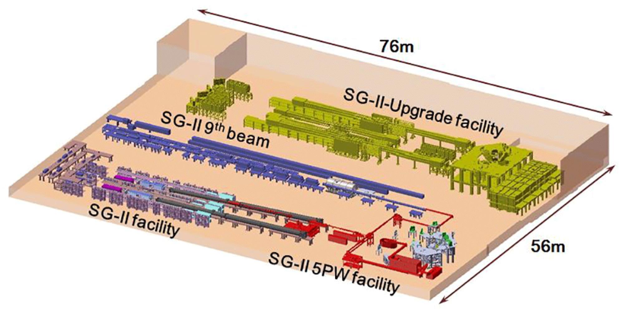
In this report, we provide a detailed introduction on the design specifications and current performance of the Shen Guang-II 5PW (SG-II 5PW) laser facility at the National Laboratory on High Power Laser and Physics (NLHLP), Shanghai Institute of Optics and Fine Mechanics, Chinese Academy of Sciences (SIOM, CAS). NLHLP has studied solid-state laser technologies and engineering for half a century and has developed SG series laser drivers for the research on inertial confinement fusion (ICF) in China. As shown in Figure  and currently consists of SG-II, SG-II 9th beam, SG-II-Upgrade (SG-II-UP) and SG-II 5PW laser facilities. There used to be another laser facility named SG-I which ex-served in 1995. All of the laser facilities of the SG series except for the SG-II 5PW are based on Nd: glasses that pumped by xenon lamps, and operate in single shot (
 ). The SG-II facility is capable of delivering pulses of 6 kJ at 1053 nm (
 ) and 2.4 kJ at 351 nm (
 ) when the pulse duration is 1 ns with all of the eight laser beams, one of which can provide probe laser pulses of several joules in 100 ps at 266 nm (
 ). The SG-II 9th beam is a multi-functional laser facility, and it can provide pulses of 5.13 kJ at
  and 3 kJ at
  in 3.4 ns. In addition, it can provide probe lasers for physical experiments with tunable pulse bandwidths of 30 ps, 80 ps and
  . SG-II-UP facility consists of eight nanosecond pulse beams and one picosecond petawatt pulse beam. The eight nanosecond beams regularly operate at 40 kJ/3.3 ns/
 and 25 kJ/3.3 ns/
 . The maximum
  fluence density achieved now is
  with the beam size of
  . The picosecond petawatt beam can deliver pulses of 1 kJ/10 ps, 700 J/3 ps and 350 J/1 ps at
  after compression, similar to that obtained by the Omega EP at the University of Rochester[
 and 17.5 kJ/20 ns/
 with beam aperture
  . The maximized fluence density is up to
  and such a value is at the same level of those highest in the world[
The design of the SG-II 5PW facility is shown in Figure  LBO crystal, a chirped pulse that has energy higher than 250 J and a bandwidth broader than 40 nm is aimed. The beam is expanded to dimensions of
  by spatial filter 5 (SF5) before being injected into the adaptive optics (AO) and compressor, which can deliver 150 J/30 fs pulses. In order to satisfy the demands of strong field experiments, the focused intensity is designed to
  and the energy concentration is 50% in twice diffraction limitations (2DL). At the focal spot, pulse contrast of larger than
  is required. An integrated software and user-friendly interface have been developed including diagnosis, collimation and measurement systems. Real-time online data in all units, including the state of affairs, amplified pulse energy, spectrum, pulse waveform, near field and far field are automatically collected, processed and stored[
Sign up for High Power Laser Science and Engineering TOC. Get the latest issue of High Power Laser Science and Engineering delivered right to you!Sign up now
3 Sub-system design and performance
3.1 Front end
The front end consists of an oscillator, pulse selector, stretcher, first stage OPCPA, pre-compressor, laser based on Nd:YAG for the OPA pump and attached spatial filters. The mode-locked Ti:sapphire oscillator operates at 78 MHz and produces 150 mW seed pulses for both signal amplification chains and photoelectric clock signal of the whole system. The oscillator provides  pulses at 808 nm that have a duration of 10 fs and FWHM spectrum bandwidth about 100 nm. A Pockels cell as a pulse selector is attached to reduce the repetition rate of OPA incident to a single shot and it operates synchronously with the master amplifier in experiments.
A four-pass Öffner stretcher is employed and shown in Figure  . The signal energy per pulse is approximately 0.2 nJ after the stretcher.
The signal beam is shrunk to  in round and injected into the first stage OPCPA (OPA-I) that includes LBO and BBO crystals as preamplifiers. The laser based on Nd:YAG glass provides spatio-temporal super-Gauss profile pulses at 1064 nm at 1 Hz repetition rate (Figure
  ,
,  ), are aligned successively in a configuration as shown in Figure
  and spatial overlap among signal, idler and pump pulses. The noncollinear angle (
 ) is set to
  in the crystal[
 in the unsaturated regime and the signal energy per pulse exceeds 2 mJ. With the waveform of approximate Gaussian profile (black line in Figure
The lens-based telescope SF1 then expands the signal beam to a diameter of 10 mm in order to match the pump beam diameter of 8.5 mm. Two type-I phase-matched BBO crystals are aligned in a configuration with an internal noncollinear angle of  . The BBO crystals are 15 mm in length and phase-matched at
  . By coupling with 390 mJ pump pulses (intensity of
  , well below the damage threshold), the signal pulses are further boosted to 130 mJ, and the total pump-to-signal conversion efficiency becomes
  . With the online measurement system, the normalized near-field distribution behind the SF3 and far-field distribution are presented in Figures
  ). The signal temporal bandwidth increases to 1.63 ns (green line in Figure
  covers the region of 784 nm to 846 nm (see green line in Figure
  at a repetition rate of 1 Hz and achieves a hundreds of millijoules chirped pulse that is expected to be compressed for the several-terawatt experimental platform.
As a further explanation, both LBO and BBO in our opinion have gain bandwidth large enough to support the compressed duration of 30 fs. On the other hand, the gain bandwidth is larger than the soft spectrum clipping of the compressor. We choose LBO as the medium of high gain OPA stage, because LBO is of higher damage threshold and the pump beam diameter on LBO can be much smaller than that of BBO. In this way, the energy of the pump pulse is smaller for high gain stage so that more energy left from the pump laser can be provided for the lateral high energy BBO-based OPA stages. In the future, we will update the Nd: YAG-based pump laser, and the LBO crystals are planned to be replaced by BBO crystals for a broader spectrum. All of the LBO and BBO crystals are cut with  wedge angles at the rear faces and coated on the surfaces with 532 nm and 808 nm broadband antireflective films to suppress the parametric oscillation. The spatial filters between the stages, including SF1–SF5, are aligned with the pinholes to suppress the high-frequency modulations. Owing to the spatially dispersive characteristics, the optical parametric fluorescence (OPF) that generates in the amplification and transmits as high-order angular spectra can also be significantly suppressed by the pinholes in the spatial filters. The pre-compressor, located behind SF2, consists of two pairs of gold-coated diffraction gratings successively arranged[
 , and the gratings are of
  and sizes of approximately
  and
and  with the incidence angle
  . The pre-compressor is used to compensate the mismatch between the stretcher and master compressor. By a precise regulation, not only the shortest pulse width can be achieved, but also the third-order dispersion can be tuned to eliminate its effect on the contrast degeneration at the front edge of the compressed pulse. The optimal transmission efficiency of the pre-compressor of
  is equal to that of the master compressor. So 90 mJ chirped pulses that have a diameter expanded to
  by SF3, are injected into the second OPCPA stage (OPA-II).
3.2 PW OPA-II
The second OPA stage is designed to realize 1 PW (compressed 30 J/30 fs) with the SHG of the 7th beam of SG-II facility as the pump source (Figure  after the Nd:glass amplifier that is capable to provide a 200 J pulse at 1053 nm[
 and
and  , in which
  is the average intensity,
  is the maximal intensity,
  and
and  are the discrete dot numbers in the fixed region, and
  is the measured intensity corresponding to the point (
 ). A numerical analysis shows that the FF and FBC of pump pulses are 0.7546 and 0.26, respectively.
A state-of-the-art OPA based on a 19-mm-thick LBO is adopted in a type-I phase-matching noncollinear configuration in  and
and  and the noncollinear angle is
  in the crystal [
 in fluence intensity, and the gain reached a value of 550. The pump-to-signal conversion efficiency is 41.9%, which to the best of our knowledge is the highest among the values reported for OPCPA facilities. The online measurement system provides the energy statistics of both signal and pump pulses for 13 shots in Figure
The precise synchronization and critically phase-matched alignment are required for high conversion efficiency. For OPA-II of SG-II 5PW, the synchronization of 100 ps (RMS) is precisely enough. The mismatches of noncollinear angle and phase-matching angle must be, respectively, smaller than  and
and  , which are determined by the acceptance angle in LBO crystal. The mismatch of noncollinear angle is determined by the monitoring precision on the beam pointing of the signal and pump beams, while the mismatch of phase-matching angle is determined by the mechanical stability of the crystal clamp. The auto-collimation system is applied to adjust the beams pointing before shots with a correction precision for state recovery about
  , which is much smaller than the acceptance angle (
 ). In addition, the crystal length as well as the incident signal and pump pulses characteristics, including the energy, spatial–temporal profiles and wavefronts, should be taken into consideration. In order to improve the operation security, stability and conversion efficiency of the SG-II 5PW facility, the effects of the pump pulse near-field property and energy fluctuation on the OPCPA are numerically simulated along the crystal length, using parametric coupling wave equations[
 around 120 J (Figure
Additional simulations on FF and FBC are performed when the incident signal and pump pulses are set in ideal spatial–temporal super-Gaussian profiles so that we can quantitatively reveal which incident pulse affects the near-field distribution performance of the OPCPA-II to a greater extent. As shown in Figure
| Crystal length (mm) | Signal energy (J) | Chirped duration (ns) | Spectrum bandwidth (nm) | Conversion efficiency | Compressed duration (fs) | Compressed power (PW) | |
|---|---|---|---|---|---|---|---|
| DKDP | 35 |  | 1.3 | 62 | 37% |  | 5 |
| LBO | 13 |  | 2 | 85 | 45% | 20 |  |
Table 2. Comparison between LBO and DKDP calculations in OPA-III.
3.3 Master amplifier under construction
We aim to use the 9th beam of the SG-II facility for the pump of the master amplifier that can provide a compressed 5 PW (150 J/30 fs) pulse. The Nd:glass amplification chain in the 9th beam has powerful abilities to achieve pulse energy larger than 5 kJ and a pulse width that is tunable in the range 1–3 ns at 1053 nm with an arbitrary waveform that can be controlled in both spatial and temporal domains[ after the SF9. A large aperture of
  LBO is required by numerical simulation for the high energy low-gain OPA, while the highest reported crystal size is
  [
[
3.4 Master compressor and contrast measurement
The master compressor contains four pieces of gold-coated gratings that have a size of
  . The gratings are aligned in a zigzag configuration, and placed in a tank that has a diameter of 1.7 m and a length of 4.9 m. The guaranteed vacuum degree is
  bar during operation (Figure
  and realizes output pulses that are temporally near the Fourier transform limitation. For the incident angle of
  , the intensities on the surface are smaller than
  and
and  for the first and last pieces of gratings, respectively, when all three amplifiers operate (smaller than half of the damage threshold).
The compressed pulse traces, measured by an autocorrelator, are shown in Figure  ), which in our opinion mainly derives from the integral effect of chromatic aberrations. The chromatic aberrations are due to all of the lens-based spatial filters. In the future, an aberration pre-compensation unit will be installed in front of SF3 and numerical simulation indicates its effectiveness. Assuming that energy of the side pulse and uncompressed pedestal is ignorable, the compressed pulse energy is 37.2 J and the peak power is up to 1.76 PW. An appropriate contrast is highly demanded for physical experiments [
 . It is featured that both pulse width and contrast are measured with the whole beam diameter by shrinking the beam from
  to
to  . These measurements with the whole beam diameter in large-aperture ultrashort laser facilities are reported for the first time, to the best of our knowledge[
| SF1 | SF2 | SF3 | SF4 | SF5 | |
|---|---|---|---|---|---|
| Size of incident beam (mm) |  |  |  |  |  |
| Focal length of incidence lens (mm) | 240 | 700 | 400 | 2480 | 2860 |
| Focal length of output lens (mm) | 960 | 1930 | 1500 | 6000 | 5720 |
| Size of output beam (mm) |  |  |  |  |  |
| Propagation time difference (fs) | 2 | 5 | 78 | 127 | 566 |
Table 3. Design of multiple-stage spatial filters in SG-II 5PW system.
Next we analyze the temporal contrast in different time regions. Scattering in grating based stretchers has been identified as a source of asymmetrical pedestal around amplified pulses. According to Ref. [ to
to  amplitude. The contrast of Figure
  in the 100 ps range, so the asymmetrical pedestal owing to the scattering in the grating based stretcher is covered up. The temporal pedestal before 20 ps, ahead of the main pulse, was mainly caused by the parametric fluorescence from OPCPA. The leading edge of the main pulse that has dimensions of few picoseconds was influenced by the residual high-order dispersion and system-wide spatio-temporal couplings among the spatial filters, compressor and focusing optics [
 square shape, by five stages of spatial filters (SF1–SF5). The propagation time difference (PTD) is defined by the time delay between the pulse in the center of the beam and that at the edge. The PTD of each spatial filter was calculated according to Ref. [
3.5 Adaptive optics and focusing
The AO system in the SG-II 5PW laser facility is utilized to correct both static and dynamic wavefront aberrations and thus to improve the focusing characteristics. The wavefront correction is extremely crucial for large-aperture ultrashort lasers, as the aberrations of the chirped pulses differ not only for spatial regions but also temporally for various wavelengths that cover a wide range. In the SG-II 5PW facility, a deformable mirror (clear aperture:  ) that consists of 77 piezoelectric ceramic transducer (PZT) actuators fabricated by Institute of Optics and Electronics (IOE, CAS) as well as a Hartmann sensor is located at the master compressor entrance (Figure
Using the AO system, the static wavefront aberrations, described by peak to valley (PV) and RMS at 808 nm, respectively, are first improved from (6.257  , 0.960
  ) to (0.661
  , 0.111
  ) when all of the OPA are not operated (Figures
  , 0.281
  ) when both OPA-I and OPA-II are operated. The profiles of the focal spots as well as the encircled energy curves, which are calculated by Fourier transform corresponding to Figures
  with the static wavefront correction to
  with the dynamic wavefront pre-compensation. Therefore, another Hartmann sensor is planned to be set after the focusing spot to evaluate the jitter of dynamic aberrations so that the focusing characteristics can be further improved by AO system in real time.
After the closed-loop correction by the AO system and compressor, the laser beam is focused by an OAP mirror that has a focal length of 800 mm and  /1.95 into the target chamber as shown in Figure
  (FWHM) without wavefront correction, the spot quality is greatly improved with the AO system and the spot size is
  (FWHM) (see Figure
  at the focal spot with a compressed pulse of 1.76 PW. The SG-II 5PW facility provides 13 shots for high energy physics experiments, and the laser proton acceleration is on average
  , which is maximized to
  for a
for a  copper target. The experimental results when radio-chromic film (RCF) interacted with the accelerated protons indicate that the intensity on the target is up to
  , approximately two orders of magnitude lower than the calculated value of
  [
[
The distinction between the calculated intensity and real intensity that is indicated by laser proton acceleration, results from two possible issues. First, the focal spot shown in Figure  in diameter. We believe that the decrease of the intensity at the target is mainly due to the optical path drift, which is caused by the vacuum chamber deformation. The OAP’s focal performance is very sensitive to the drift. In order to analyze the focal characteristics, a numerical model based on a three-dimensional (3D) ray tracing is developed (Figure
  when the angular deviation of the incident light and OAP is
  or when there is a
  deviation from the focal plane. Therefore, the angular and focal plane deviations should be less than
  and
and  in practice. Developing methods to improve the adjustment precision of OAP in the vacuum chamber is a subject of the future work. Second, the contrast at the focal spot should be further improved to values larger than
  .
.
4 Conclusion
In this paper, we presented the current performance of the SG-II 5PW facility fully based on OPCPA in the nanosecond domain. The prior two optical parametric amplifiers have realized a chirped-pulse energy of 49.7 J and a spectrum bandwidth up to 85 nm. In the PW-scale OPA, the pump-to-signal conversion efficiency is 41.9%, which is the highest among all reported values for OPCPA systems. For the first time, we reported duration and contrast measurements with the whole beam diameter for PW-class facilities. It was demonstrated that the peak power of the compressed pulse is higher than 1.76 PW (37 J/21 fs). The static focal spot was  after the closed-loop correction performed by the AO. The SG-II 5PW facility has succeeded in providing 13 shots for high energy physics experiments. In addition, laser proton acceleration was achieved. This indicates that the effective focused intensity for experiments has exceeded
  and the contrast was not severely degenerated at the focal spot. In the future, both of the focusing characteristic and contrast are big issues for the whole system. The OPA-III to realize 5 PW now is under construction. The large-aperture LBO is preferred as the gain media, while DKDP of high level deuteration is an alternative proposal.
References
[1] C. Danson, D. Hillier, N. Hopps, D. Neely. High Power Laser Sci. Eng., 3, e3(2015).
[2] G. Mourou, T. Tajima. Science, 331, 41(2011).
[7] https://www.eli-beams.eu/en/media/news/livermore-meets-key-milestone-delivery-worlds-high/
[10] J. Moses, C. Manzoni, S. Huang, G. Cerullo, F. X. Kärtner. Opt. Express, 17, 5540(2009).
[11] http://www.xcels.iapras.ru/index.html
[19] Y. Gu, F. Zhang, L. Shan, B. Bi, J. Chen, L. Wei, J. Li, Z. Song, Z. Liu, Z. Yang, M. Yu, B. Cui, Y. Zhang, H. Liu, D. Liu, W. Wang, Z. Dai, Y. Yang, L. Yang, F. Zhang, X. Wu, K. Du, W. Zhou, L. Cao, B. Zhang, J. Wu, G. Ren, H. Cai, S. Wu, L. Cao, H. Zhang, C. Zhou, X. He. High Power Laser Part. Beams, 27, 110101(2015).
[20] J. Zhang, D. Liu, B. Zhu, S. Tang, Y. Gao. Opt. Eng., 55, 036108(2016).
[21] Y. H. Wang, X. Pan, X. C. Li, Z. Q. Lin. Chin. Phys. Lett., 26, 024211(2009).
[23] B. Zhao, Y. Jiang, K. Sueda, N. Miyanaga, T. Kobayashi. Opt. Express, 16, 18863(2008).
[24] E. B. Treacy. IEEE J. Quant. Electron., 5, 454(1969).
[25] D. Huang, W. Fan, Z. Lin. Chin. J. Lasers, 38(2011).
[26] J. Liang, R. N. Kohn, M. F. Becker, D. J. Heinzen. Appl. Opt., 49, 1323(2010).
[28] F. Zhang, Y. Wang, M. Sun, Q. Bi, X. Xie, Z. Lin. Chin. Opt. Lett., 8, 217(2010).
[29] Z. Dongfeng, W. Li, L. Zunqi. Chin. J. Lasers, 38, 0702001(2011).
[30] X. Liang, M. Sun, J. Kang, J. Zhou, X. Xie, J. Zhu, Z. Lin. Conference on Lasers and Electro-Optics, OSA Technical Digest(2017).
[32] F. Salin, P. Georges, G. Roger, A. Brun. Appl. Opt., 26, 4528(1987).
[34] V. Bagnoud, F. Wagner. High Power Laser Sci. Eng., 4, e39(2016).
[35] E. J. Divall, I. N. Ross. Opt. Lett., 29, 2273(2004).
[38] P. Zhu, X. Xie, X. Ouyang, J. Zhu. High Power Laser Sci. Eng., 2, e42(2014).
[39] P. Zhu, X. Xie, J. Zhu. Acta Opt. Sin., 37, 0914005(2017).
[40] Z. Bor. J. Modern Opt., 35, 1907(1988).
[42] A. Macchi, M. Borghesi, M. Passoni. Rev. Modern Phys., 85, 751(2013).

Set citation alerts for the article
Please enter your email address
© Copyright 2018-2021 | Chinese Laser Press. All Rights Reserved 沪ICP备15018463号-20