Controlling quantum dots’ emission, nanostructure, and energy level alignment to achieve stable and efficient blue emission is of great significance for electroluminescence devices but remains a challenge. Here, a series of blue ZnCdSeS/ZnS quantum dots was optimized in preparation by taming their nucleation and growth kinetics. Controlling anion precursor reactive properties to modulate quantum dots’ nucleation and growth tailors their alloy core and continuous gradient energy band nanostructure. These results not only elevate the thermal stability of blue quantum dots but also further enhance the injection/transportation of carriers and improve the radiative recombination efficiency in the device. The blue ZnCdSeS/ZnS quantum dots applied in light-emitting devices show superior performance, including maximum current efficiency and external quantum efficiency of, respectively, 8.2 cd/A and 15.8% for blue, 2.6 cd/A and 10.0% for blue-violet, and 10.9 cd/A and 13.4% for sky-blue devices. The blue and sky-blue devices exhibit lifetimes of more than 10,000 h. The proposed methodology for tailoring quantum dots is expected to pave new guidelines for further facilitating visible optoelectronic device exploration.
1. INTRODUCTION
Quantum dot light-emitting devices (QLEDs) have enormous potential for application in display and lighting fields because of their color saturation, high brightness, tunable visible light spectrum, and low fabrication cost [1–8]. For display devices, it must be required to have high external quantum efficiency (EQE, ), surpassing the threshold values for both brightness () and lifetime () simultaneously [5,9–13]. To develop QLEDs to meet next-generation display requirements, many works show that their EQE can be increased to 30.9% for red QLEDs, 23.9% for green devices, and 19.8% for blue devices [14–16]. Still, in blue devices based on ZnCdS/ZnS quantum dots (QDs), due to the deep energy level, wide bandgap, and high working voltage, the device lifetime is lower than its commercial application 10,000 h standards [9,17,18].
Tailoring the core composition and shell barrier alignment of QDs on demand enables the control of not only the energy level and emission of QDs, but also the recombination dynamics of charge carriers within QDs [19–21]. Most importantly, tailoring QDs’ nanostructure to modulate the transport and recombination characteristics of charge carriers across QDs and neighboring charge transport nanofilms is key to the ultimate successful application in LEDs [20,22–24]. However, it is still a comprehensive challenge to precisely design CdSe-based core/shell QDs with different shell layer thicknesses to achieve customized blue emission to coincide with QLED applications. This is due to the reduction of the quantum confinement effect during the shell growth process and the redshift of the spectrum [25,26]. The mild deep electron confinement and shallow hole confinement of QDs are more favorable for the balance of electron and hole injection into devices and have been found to be significant for improving the performance of QLEDs [27–29]. However, there are limited ways to control the nucleation and growth of alloy QDs, which hinders the accurate regulation of the gradient energy band alignment distribution and restricts the practical application of blue alloy QDs [30].
Here, we demonstrate a novel method for preparing high-quality blue ZnCdSeS/ZnS alloy QDs with excellent photophysical and chemical characteristics, achieving emission and customizable nanostructures with high photoluminance quantum yield (PL QY). We tame the nucleation and growth of blue QDs through controlled anion precursor reactivity to precisely tailor their energy levels and nanostructures. The tailored blue QDs have enhanced thermal stability and charge injection/transport for efficient charge recombination, improving the EQE and lifetime of the QLEDs. The resulting devices show a maximum current efficiency and EQE of up to, respectively, 8.1 cd/A and 15.8% for blue, 10.0% for blue-violet, and 13.4% for sky-blue QLEDs. More importantly, the QLED lifetimes were shown to be 10,420 h for the blue device and 11,287 h for the sky-blue device with an initial brightness of . We anticipate that our strategy for QD preparation will further make blue QLEDs for commercial display applications.
Sign up for Photonics Research TOC. Get the latest issue of Photonics Research delivered right to you!Sign up now
2. RESULTS AND DISCUSSION
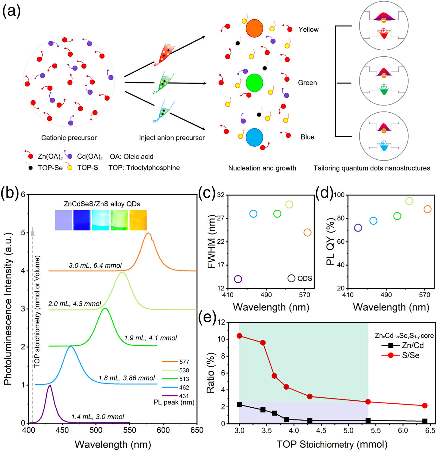
The summarized synthetic procedure outlined for preparing gradient alloy QDs with colors from ultraviolet to yellow is shown in Fig. 1(a). The ZnCdSeS/ZnS QDs are synthesized by rapidly injecting trioctylphosphine (TOP)-(Se+S) into the mixed cation precursor of zinc oleate and cadmium oleate with heating at 300°C. We found that as the injected precursor concentration increases (decreasing the TOP stoichiometry) and the molar amount of anion remains constant, the synthesized QDs gradually shift from the blue to violet light emission range. On one hand, because the bond dissociation energies of the Zn-S (224.8 kJ/mol), Cd-S (208.5 kJ/mol), and Zn-Se (170.0 kJ/mol) bonds are greater than that of the Cd-Se bond (127.6 kJ/mol) [31], the CdSe-based QD core was formed first, and then the Zn-S/Se shell grows on the surface of the core and diffuses into the core to form an alloy structure simultaneously [32]. On the other hand, increasing the concentration of anion precursors would shorten the nucleation time of QDs, leading to rapid consumption of anion and cation precursors in the reaction microenvironment, resulting in the formation of QD nuclei with different compositions and different fluorescence emissions. At the same time, the proportion of unreacted precursor composition changes, and gradient shells with different compositions and nanostructures are thus grown on the core. At the same time, the composition of different cores changes the precursor composition for the growth of QD alloy shells, and finally alloy QDs are formed with different composition gradient structures.
Figure 1.(a) Schematic diagram of the preparation process of cores and gradient ZnCdSeS/ZnS alloy QDs with different emissions and nanostructures. (b) ZnCdSeS/ZnS alloy QDs with the evolution of spectra from violet to yellow. Inset: PL images of ZnCdSeS/ZnS alloy QDs with different emission colors. (c) Full width at half maximum (FWHM) and (d) PL QY of ZnCdSeS/ZnS alloy QDs with the given peak. (e) Zn/Cd and S/Se composition ratio of cores based on ICP-OES data.
Taming nucleation and growth of QDs to regulate their gradient alloy composition would significantly tailor the energy band and level of the QDs from the inner core to outer shell. Following the nucleation and growth mechanism, a series of ZnCdSeS/ZnS alloy QDs with emission from violet to yellow and varying shell bandgaps is prepared via a one-pot successive growth method [Fig. 1(b)]. With the gradual decrease of TOP-(Se+S) concentration (, mmol), the fluorescence emission peak of QDs redshifts from 431 nm (TOP: 3.0 mmol) to 576 nm (TOP: 6.4 mmol), and the fluorescent images gradually change from purple to yellow [Fig. 1(b) inset]. Utilizing the tunable stoichiometry of TOP as an anion precursor solvent injected into a cationic mixture for faster and more uniform QD nucleation and growth in a reaction environment, we avoid the inhomogeneity of QDs’ structure and composition. Therefore, the QDs were prepared by modulating the nucleation and growth, enabling optimization of the composition gradient and thickness of the shell, obtaining narrow emission spectra [, Fig. 1(c)] and high PL QY [, Fig. 1(d)], and maintaining a regular profile and reasonable size distribution (see Fig. 6 in Appendix A).
To deeply understand the mechanism of ZnCdSeS/ZnS alloy QDs’ nucleation and growth kinetics, the elemental analysis by inductively coupled plasma optical emission spectroscopy (ICP-OES) and X-ray diffraction (XRD) was applied to analyze the molar ratio of Zn/Cd and S/Se in the core and the structure of ZnCdSeS/ZnS alloy QDs, respectively (see Figs. 7 and 8 in Appendix A). Figure 1(e) shows the evolution of the composition of Zn/Cd and S/Se for these QDs by injecting different anion concentrations (only change TOP stoichiometry). When the injection TOP stoichiometry increases, the Zn/Cd ratio of the core reduces from 10.4 to 2.1, while with S/Se from 2.3 to 0.3, the QDs spectra redshift. Also, the stoichiometry of TOP varies from 3.0 to 5.4 mmol, and the ratio of Zn/Cd and S/Se in the QD core decreases rapidly until it tends to stabilize when the stoichiometry is greater than 5.4 mmol. The composition of the core showed an unbalanced ratio of Zn/Cd and S/Se (Table 1). This means increasing the Zn/Cd (S/Se) element ratio will cause the spectrum to blueshift; otherwise, it will redshift. The ZnCdSeS/ZnS alloy QDs with zinc blende structure and uniform size eventually formed through continuous gradient shell growth (see Fig. 8 in Appendix A). Specifically, this strategy is undoubtedly beneficial to facilitate the ratio or concentration of precursors to modulate the nucleation and growth kinetics of alloy QDs, and realize tailoring the nanostructure of QDs at specific wavelengths.
ZnxCd1−xSeyS1−y Cores with a Chemical Composition
TOP (mmol)
Zn
Cd
Se
S
QD Core Composition
3.00
0.69
0.31
0.08
0.92
3.43
0.62
0.38
0.09
0.91
3.64
0.56
0.44
0.15
0.85
3.86
0.35
0.66
0.19
0.81
4.29
0.29
0.71
0.24
0.76
5.36
0.2
0.71
0.28
0.72
6.43
0.24
0.76
0.32
0.68
Following the principles of tunable nucleation and growth, we synthesized continuous gradient alloy ZnCdSeS/ZnS blue QDs with an emission peak of 441 nm (blue-violet), 456 nm (blue), and 466 nm (sky-blue) (see Fig. 9 in Appendix A). The gradient structure of QDs with a mid-interfacial layer and thickness of the shell relaxes their lattice strain and suppresses interface defects, improving their PL QY. The nucleation and growth of the ZnCdSeS/ZnS QDs were conducted in a single batch with the difference in reaction rates of the cationic precursor by utilizing different stoichiometries of TOP; QD cores exhibit different compositions, and the shell gradually changes from a narrow to wide bandgap, forming QDs with different emissions and nanostructures. Figures 2(a)–2(c) show the spectral evolution of blue-violet, blue, and sky-blue QDs growing from nucleation to shell, respectively. The inset is a schematic diagram of their energy arrangement, which qualitatively describes the confinement effect of QD energy band changes on the regulation of QD exciton wave functions. These cores were prepared to give emissions at 443 nm, 453 nm, and 473 nm, and then the wide bandgap shell was grown on the core and interfused into it to produce ZnCdSeS/ZnS alloy QDs. Moreover, the emission peaks of QDs during the continuous growth shell continuously shifted to 437 nm, 457 nm, and 469 nm, respectively, controlled by the ratio and concentrations of Se and S. Undoubtedly, the change of composition of the core with different bands modulates the deposition gradient during the shell growth, tailoring the nanostructure and energy band array.
Figure 2.Time-dependent PL spectra of (a) blue-violet, (b) blue, and (c) sky-blue ZnCdSeS/ZnS alloy QDs. Inset: schematic of QDs’ energy alignments and exciton delocalization. (d) Time-resolved PL decay kinetics, (e) temperature-dependent PL peak, and (f) intensity of blue-violet, blue, and sky-blue ZnCdSeS/ZnS alloy QDs.
Figure 2(d) illustrates the time-resolved PL decay kinetics results of blue-violet, blue, and sky-blue ZnCdSeS/ZnS alloy QDs. For comparison, the QDs were well fitted with a double-exponential decay function, gaining lifetimes of 15.8, 15.5, and 16.6 ns for blue-violet, blue, and sky-blue, respectively, in which the goodness of fit () was set to less than 1.3 [33] (Table 2). To further qualitatively analyze how nanostructures regulate their optical properties and thermal stability, we conducted temperature-dependent PL measurements [Figs. 2(e) and 2(f)]. The spectra featured emission peak redshifts with elevated temperature. It is especially obvious that when the temperature exceeds 350 K, the sky-blue QDs begin to have spectral redshifts, which is far ahead of blue and blue-violet at 450 K [Fig. 2(e)]. From room temperature to 573 K, the spectral redshift is 6 nm, 6 nm, and 12 nm for blue-violet, blue, and sky-blue, respectively. Moreover, when the temperature rises to 450 K, the PL intensities of the blue-violet, blue, and sky-blue QDs remain at 80%, 92%, and 82% of the initial value, respectively [Fig. 2(f)]. These achievements confirm that the energy band alignment of QDs regulates the delocalization of excitons, as expected, exhibiting extraordinary thermal stability and excellent color purity.
Lifetimes and Fractional Contribution of Different PL Decay Channels for Sky-Blue, Blue, and Blue-Violet ZnCdSeS/ZnS Alloy QDs in Solutiona
Color
(ns)
(ns)
(%)
(%)
(ns)
Sky-blue
8.74
19.63
27.54
72.46
16.6
1.11
Blue
6.23
17.73
19.31
80.69
15.5
1.23
Blue-violet
6.46
18.72
23.47
76.53
15.8
1.25
and , nonradiative recombination decay component and its proportion; and , radiative recombination component and its proportion; , corresponding PL lifetime.
Incorporating the blue ZnCdSeS/ZnS alloy QDs into LEDs, we further study the influence of tailoring QDs’ nanostructure on the turn-on, brightness, and lifetime of devices. The schematic illustration of structure and the energy level diagram of QLEDs show the following device architecture: indium tin oxide (ITO)/poly (ethylenedioxythiophene) (PEDOT): polystyrene sulphonate (PSS)/poly[9,9-dioctyl-fluorene-co-N-(4-butylphenyl)-diphenylamine] (TFB)/QDs/ZnO/Al cathode [Figs. 3(a) and 3(b)]. Atomic force microscopy (AFM) was used to characterize roughness of PEDOT: PSS, TFB, QD, and ZnO films in multilayer device configurations. For each layer, the height image and the pseudo-three-dimensional image are shown in Fig. 4; note that these films have pin-hole-free features, and root mean square roughness is in the range of 0.5–2.0 nm for charge transport layers [Figs. 4(a)–4(c)] and 1.4–1.7 nm for emission layers [Figs. 4(d)–4(f)]. ZnCdSeS/ZnS alloy QDs undergo surface passivation before use. The surface passivation could eliminate the surface defects of QDs and boost full-color QLEDs, which have already been reported in our previous work [34]. To evaluate the effectiveness of hole injection from the TFB to the QD layers of electroluminescence (EL) devices [35], the energy levels of the blue-violet, blue, and sky-blue QDs were measured by using ultraviolet photoelectron spectroscopy [Fig. 3(c)]. It is found that the valence band (VB) edges vary in the order of sky-blue, blue, and blue-violet QDs, and the corresponding positions are 6.50 eV, 6.55 eV, and 7.02 eV, respectively. The higher VB edges of the ZnCdSeS/ZnS alloy QDs correspond to a decrease in the hole injection barriers from TFB into the QD layers [Fig. 3(d)], which proves that the strategy of tailoring QDs’ nanostructure and energy level promises a significantly reduced hole injection barrier in QLEDs [36–38]. Compared with the electron transport layer, the larger conduction band difference (0.5 eV) suppresses the injection of electrons into the QD layers, which is beneficial to reduce the charge-induced nonradiative Auger recombination of the emission layers in QLEDs and improve the stability and efficiency of the device.
Figure 3.(a) Schematic illustrating the structure and (b) energy level diagram of QLEDs. (c) Ultraviolet photoelectron spectroscopy of blue-violet, blue, and sky-blue QDs. (d) Current–voltage measurements for hole-only devices, where the devices were formed from sky-blue, blue, and blue-violet QDs. (e) Current density luminance versus driving voltage characteristics and (f) EQE as a function of luminance of the performing QLEDs based on blue-violet, blue, and sky-blue QDs.
Figure 4.AFM measurements show the root mean square (RMS) roughness for the following layers: (a) PEDOT:PSS, (b) TFB, and (c) ZnO. RMS of (d) sky-blue, (e) blue, and (f) blue-violet ZnCdSeS/ZnS alloy QDs.
Current density and luminance versus voltage characteristics of QLEDs based on the sky-blue, blue, and blue-violet ZnCdSeS/ZnS alloy QDs are presented in Fig. 3(e). The sky-blue and blue QLEDs exhibit much lower leakage current and higher injection current density than the blue-violet device. This can be attributed to the higher VB edges of the sky-blue and blue QDs, which enables better injection of charge into the QD layers. At peak EQEs, the brightness of sky-blue and blue devices at 3.6 V is and , respectively, higher than that of the blue-violet brightness of . The turn-on voltage of these devices is as low as 2.6 V for sky-blue and blue, while 2.8 V for blue-violet is slightly smaller than the bandgap of QDs, indicating that holes and electrons are effectively injected into the emission layer at low-driving voltage. Figure 3(f) presents the current efficiency and EQE versus luminance characteristics of these devices. The maxima of device current efficiency and EQE remained remarkably high at 8.2 cd/A and 15.8% () for blue, 2.6 cd/A and 10.0% () for blue-violet, and 10.9 cd/A and 13.4% () for sky-blue colors, realizing the corresponding maximum brightness of , , and , respectively (Table 3).
Summary of EL Performance, Maximum Luminance (), EQE, and Lifetime of Optimized Best Performing QLEDs
QDs
EL (nm)
()
Peak EQE (%)
Lifetime () at
Reference
ZnCdS/ZnS
455
4000
10.7
[9]
468
4890
19.8
47.4
[14]
445
4500
15.6
47 ()
[39]
ZnCdSe/ZnS/ZnS
479
14,100
16.2
355
[40]
ZnCdSe/ZnSe
482
62,600
8.05
7000
[10]
CdZnS/ZnS
454
27,753
8.92
–
[18]
CdSeS/ZnSeS/ZnS
483
/
10,000
[41]
ZnCdSeS/ZnS
443
6442
10.0
3813
This work
462
14,390
15.8
10,420
472
21,130
13.4
11,287
The EL spectra represent a redshift [Fig. 5(a)], and the blue-violet and sky-blue QLEDs exhibit a broadening of the EL spectrum, whereas the blue device remains almost unchanged to maintain high color purity. The photographs also show remarkably uniform emissions across the entire device active area [Fig. 5(a) inset]. Nonetheless, all devices exhibited very saturated and pure colors, as demonstrated in the Commission Internationale de l’Eclairage (CIE) chromaticity diagram shown in Fig. 5(b).
Figure 5.(a) EL spectra and photographs of QLEDs, and (b) corresponding CIE coordinates of the three QLEDs. (c) Luminance versus time of operation under ambient conditions of blue-violet, blue, and sky-blue QLEDs.
To evaluate the lifetimes of QLEDs, all devices were tested under accelerated conditions at a higher initial brightness. The brightness slowly decreases from the initial value to half after the blue-violet QLEDs’ luminance from 1930 to , the blue device from 3300 to , and the sky-blue device from 2000 to , and the corresponding lifetimes were 26.4, 29.2, and 73.6 h, respectively [Fig. 5(c)]. These results are fitted by an empirical equation [42], obtaining an acceleration factor of 1.68. According to the acceleration formula, the lifetimes of blue and sky-blue QLEDs are shown to be over 10,000 h with an initial brightness of , and a lifetime of 10,420 h for the blue and 11,287 h for the sky-blue device. The operating lifetimes of the blue QLEDs exceed the 10,000 h requirement for display applications. Compared with previously reported blue QLEDs, to the best of our knowledge, this strategy achieves longer lifetimes over the existing values in literature (Table 3).
3. CONCLUSION
In summary, we have developed a novel methodology for the customization of blue ZnCdSeS/ZnS alloy QDs with controlled energy band alignment by taming nucleation and growth kinetics. The blue QDs in LEDs exhibited high efficiencies of charge injection/transport, reaching the maximum EQE of up to 15.8% for blue, 10.0% for blue-violet, and 13.4% for sky-blue QLEDs. Importantly, the blue and sky-blue devices show excellent values for high brightness of and , and the corresponding outstanding lifetimes of 10,420 h and 11,287 h at , respectively. These results indicate that the tunable nucleation and growth characteristics allow one to design alloy QD nanostructure profiles under specific emissions, thereby overcoming the limitation of emission material choice for QLEDs. We believe that our work shows the findings and advances in blue QD nanostructure engineering, which is a crucial step toward the realization of QLED displays.
4. EXPERIMENT
Synthesis of the ZnCdSeS/ZnS alloy QDs: QDs with blue emission were prepared by the following method [1]. Typically, 0.2 mmol of cadmium oxide and 4 mmol zinc acetate () were placed with 5 mL of oleic acid (OA) in a 100 mL flask, then 15 mL of octadecene was injected into the reaction flask and heated to 170°C, and stirring lasted for 20 min under a nitrogen flow, yielding a clear mixture solution of and . Then the mixture was heated up to 300°C. Afterward, 0.2 mmol of Se and 3.8 mmol of S were dissolved in 1.8 mL of TOP, then swiftly injected into the mixture solution and kept at 300°C for 10 min to form the blue ZnCdSeS/ZnS alloy QDs with a chemical-composition gradient, and then the reactor was lowered to room temperature. Finally, purification procedures were performed by using the dispersion/precipitation method with a solvent ratio of toluene/ethanol and repeated five times. The prepared QDs were then dispersed in toluene after post-treatment by our previously reported method [34], and were ready for further usage. The synthesis procedure of ZnCdSeS/ZnS alloy QDs with different emissions was similar except for the different stoichiometry of TOP.
Sign up for Photonics Research TOC. Get the latest issue of Photonics Research delivered right to you!Sign up now
Synthesis of zinc oxide (ZnO) nanoparticles (NPs): ZnO NPs were synthesized by a solution-precipitation process reported in the literature [9]. In a typical ZnO NP synthesis process, 3 mmol dissolved in dimethyl sulphoxide (0.1 mol/L) and 5.5 mmol tetramethylammonium hydroxide pentahydrate dissolved in ethanol (0.55 mol/L) were mixed and stirred for 1 h in air at 24°C. Then ZnO NPs were washed with ethanol/ethyl acetate and centrifuged (8000 r/min, 3 min). Finally, ZnO NPs were dispersed in ethanol at a concentration of 30 mg/mL and stored at for device fabrication.
QLEDs device fabrication: QLEDs were fabricated by spin coating on glass substrates with a patterned ITO anode (18 Ω/sq). The substrates were cleaned sequentially in ultrasonic baths of detergent, deionized water, chromatographic grade acetone, and 2-propanol for 15 min each, and the cleaned ITO was exposed to a UV-ozone treatment for 15 min. Then, the substrates were spin-coated with 40 nm PEDOT: PSS [filtered with a 0.45 μm poly(vinylidene fluoride) (PVDF) filter] at a spin rate of 4000 r/min for 45 s and baked at 140°C for 15 min in air, and then transferred into a -filled glove box for further spin coating of TFB, QD, and ZnO NP layers. TFB was dissolved in chlorobenzene (8 mg/mL) and stirred for 24 h before use. Afterward, TFB, QDs, and ZnO NPs were filtered with a 0.22 μm PVDF filter before use, and then spin-coated onto the TFB layer at 2000 r/min for 45 s, followed by thermal annealing at 150°C for 30 min. The QD (in toluene) layers were then spin-coated on the ITO/PEDOT: PSS/TFB layer, and the optimized emission layer thicknesses were for blue (15 mg/mL, 2500 r/min for 45 s); the ZnO NP layer was then spin-coated on the ITO/PEDOT: PSS/TFB/QDs layer and then baked at 60°C for 30 min. Finally, the multilayered device samples were loaded into a high-vacuum chamber () for deposition of an Al cathode (100 nm). To protect the devices from water and oxygen, we encapsulated the devices with UV-cured epoxy and covered them with thin glass slices.
Materials and devices characterization: steady-state PL spectra, QY, and a time-correlated single-photon counting spectrum were collected using an Edinburgh FLS920 fluorescence spectrophotometer. PL decay spectra of QD samples were diluted in toluene solution and excited by a 405 nm ps laser with a 2.5 MHz repetition rate, and the peak photon counts were set at 3000. The size of the as-synthesized QDs was obtained using a JEOL JEM-2100F transmission electron microscope (TEM) at 200 kV. The XRD spectra were obtained on a Bruker D8 diffractometer with Cu Ka radiation. ICP-OES was measured using a SPECTRO-BLUE to analyze the elemental composition of QDs. All samples were prepared by dissolving in diluted solutions. The energy levels of QDs were measured by using ultraviolet photoelectron spectroscopy (ESCALAB 250 XI). The morphologies and thicknesses of the sample films are characterized by AFM (Dimension Icon, Bruker). The current–voltage–luminance characteristics of the QLEDs were measured under ambient conditions; the EL spectra and luminance were obtained by using a PR-735 spectroradiometer (Photo Research) and a Keithley 2400 source meter to furnish the device driving voltage and to record its current density.
APPENDIX A
TEM images of the cores and the ZnCdSeS/ZnS QDs, X-ray powder diffraction pattern of the ZnCdSeS/ZnS QDs, and TEM images of the blue-violet, blue, and sky-blue ZnCdSeS/ZnS alloy QDs are shown in Figs. 6–9, respectively.
Figure 6.(a)–(e) TEM images of cores with emission spectra from violet to yellow, respectively. Inset shows the size distribution of the cores.
Figure 7.(a)–(e) TEM images of ZnCdSeS/ZnS with emission spectra from violet to yellow, respectively. Inset shows the size distribution of QDs. Scale bar: 20 nm.