【AIGC One Sentence Reading】:We propose a new method for accurately retrieving the complex transmission matrix of highly scattering media, enhancing anti-scattering focusing and image transmission performance.
【AIGC Short Abstract】:Our study introduces a novel method for accurately measuring the complex transmission matrix of highly scattering media. By incorporating regional phase differentiation, we enhance measurement accuracy, leading to improved anti-scattering focusing and reduced bit error rates in image transmission. This advancement paves the way for more precise modulation of scattered optical fields, benefiting microscopy, biomedical imaging, and optical communications.
Note: This section is automatically generated by AI . The website and platform operators shall not be liable for any commercial or legal consequences arising from your use of AI generated content on this website. Please be aware of this.
Abstract
Accurately measuring the complex transmission matrix (CTM) of the scattering medium (SM) holds critical significance for applications in anti-scattering optical imaging, phototherapy, and optical neural networks. Non-interferometric approaches, utilizing phase retrieval algorithms, can robustly extract the CTM from the speckle patterns formed by multiple probing fields traversing the SM. However, in cases where an amplitude-type spatial light modulator is employed for probing field modulation, the absence of phase control frequently results in the convergence towards a local optimum, undermining the measurement accuracy. Here, we propose a high-accuracy CTM retrieval (CTMR) approach based on regional phase differentiation (RPD). It incorporates a sequence of additional phase masks into the probing fields, imposing a priori constraints on the phase retrieval algorithms. By distinguishing the variance of speckle patterns produced by different phase masks, the RPD-CTMR can effectively direct the algorithm towards a solution that closely approximates the CTM of the SM. We built a prototype of a digital micromirror device modulated RPD-CTMR. By accurately measuring the CTM of diffusers, we achieved an enhancement in the peak-to-background ratio of anti-scattering focusing by a factor of 3.6, alongside a reduction in the bit error rate of anti-scattering image transmission by a factor of 24. Our proposed approach aims to facilitate precise modulation of scattered optical fields, thereby fostering advancements in diverse fields including high-resolution microscopy, biomedical optical imaging, and optical communications.
1. INTRODUCTION
The presence of refractive index heterogeneity within a strong scattering medium (SM) deflects the photons multiple times, leading to the rapid transformation of a regular laser beam into disordered speckles [1,2]. Forming disordered speckles however is a deterministic process, that is, the light beam propagates along the intrinsic transmission channels [3–10]. This transmission channel model is mathematically equivalent to a complex transmission matrix (CTM) featuring complex entries that depict the linear coupling between the th output and th input channels [11–13]. Through precise CTM measurement and subsequent compensation of the scattering effect, researchers have successfully accomplished anti-scattering light focusing and imaging through biological tissues [14–19]. Furthermore, by harnessing the SM’s high-dimensional processing capability, significant breakthroughs have been achieved in various fields, including super-resolution imaging, optical computing, and miniature spectrometry. Notably, these advancements have contributed to substantial enhancements in the resolution of optical imaging [20–22], improved computing performance in optical neural networks [23–25], and the successful decoupling of spectral and spatial information within miniature spectrometers [26,27].
Presently, the CTM measurement methods can be broadly classified into two categories: interferometric and non-interferometric approaches [28–32]. The former utilizes phase-shifting interferometry to measure the optical field located behind the SM and subsequently resolves the CTM through a matrix transformation. Despite its utility, the interferometric method is susceptible to various disturbances such as aerodynamic fluctuations and mechanical vibrations, consequently leading to a notable degradation in the precision of CTM measurements [33]. To circumvent the above challenges, a non-interferometric method was proposed [29], in which a spatial light modulator generated a series of probing fields following random probability distribution, a camera captured the speckle patterns corresponding to each probing field, and a program retrieved the CTM using phase retrieval algorithms, including the phase retrieval variational Bayes expectation maximum (prVBEM), Gerchberg–Saxton (GS), semidefinite programming (SDP), and extended Kalman filter (EKF) [29,34–37]. Notably, the non-interferometric method exhibits robust noise immunity and has become a hot spot in the recent studies [9,38–40]. Nevertheless, conventional non-interferometric approaches have frequently suffered from slow processing speeds due to limitations imposed by the low frame rate of spatial light modulators (SLMs), such as the liquid-crystal-on-silicon SLMs, thereby impeding the pace of measurement [34]. To address this issue, researchers turned to the utilization of the amplitude-type SLM, e.g., digital micromirror device (DMD), recognized for its outstanding attributes as an SLM in terms of modulation speed, stability, spectral width, and polarization sensitivity. Unfortunately, the lack of control over the phase of the probing fields posed a significant challenge when implementing the amplitude-type SLM for non-interferometric CTM measurements [41]. Consequently, under the utilization of amplitude-type SLM, the non-convex problem in the phase retrieval algorithm became a critical concern, leading to the phase retrieval process easily converging to a local optimum and substantially undermining the accuracy of the measurement process [42].
Here, we propose a high-accuracy CTM retrieval (CTMR) method based on regional phase differentiation (RPD) to address the non-global convergence problem of amplitude-type SLM-based CTMR approaches. The proposed RPD-CTMR incorporates a sequence of additional phase masks, encompassing both phase-preserved and phase-shifted regions on the probing fields. This incorporation facilitates corresponding alterations in the speckle patterns, thus establishing a priori constraints for the phase retrieval. By distinguishing the variance of speckle patterns across different phase masks, the RPD-CTMR method effectively directs the algorithm towards consistent convergence, culminating in a solution accurately approximating the correct CTM and ensuring high-accuracy CTMR. Our comprehensive investigation involved comparative analyses between the RPD-CTMR method and the conventional one in the absence of phase constraints. Our numerical analysis indicated a substantial enhancement in CTM measurement accuracy by three orders of magnitude via the RPD-CTMR. Furthermore, the accurate measurement of the CTM during our experimental evaluation resulted in a 3.6-fold increase in the peak-to-background ratio (PBR) for anti-scattering focusing and a 24-fold reduction in the bit error ratio (BER) for anti-scattering image transmission.
Sign up for Photonics Research TOC. Get the latest issue of Photonics Research delivered right to you!Sign up now
2. PRINCIPLE OF THE RPD-CTMR
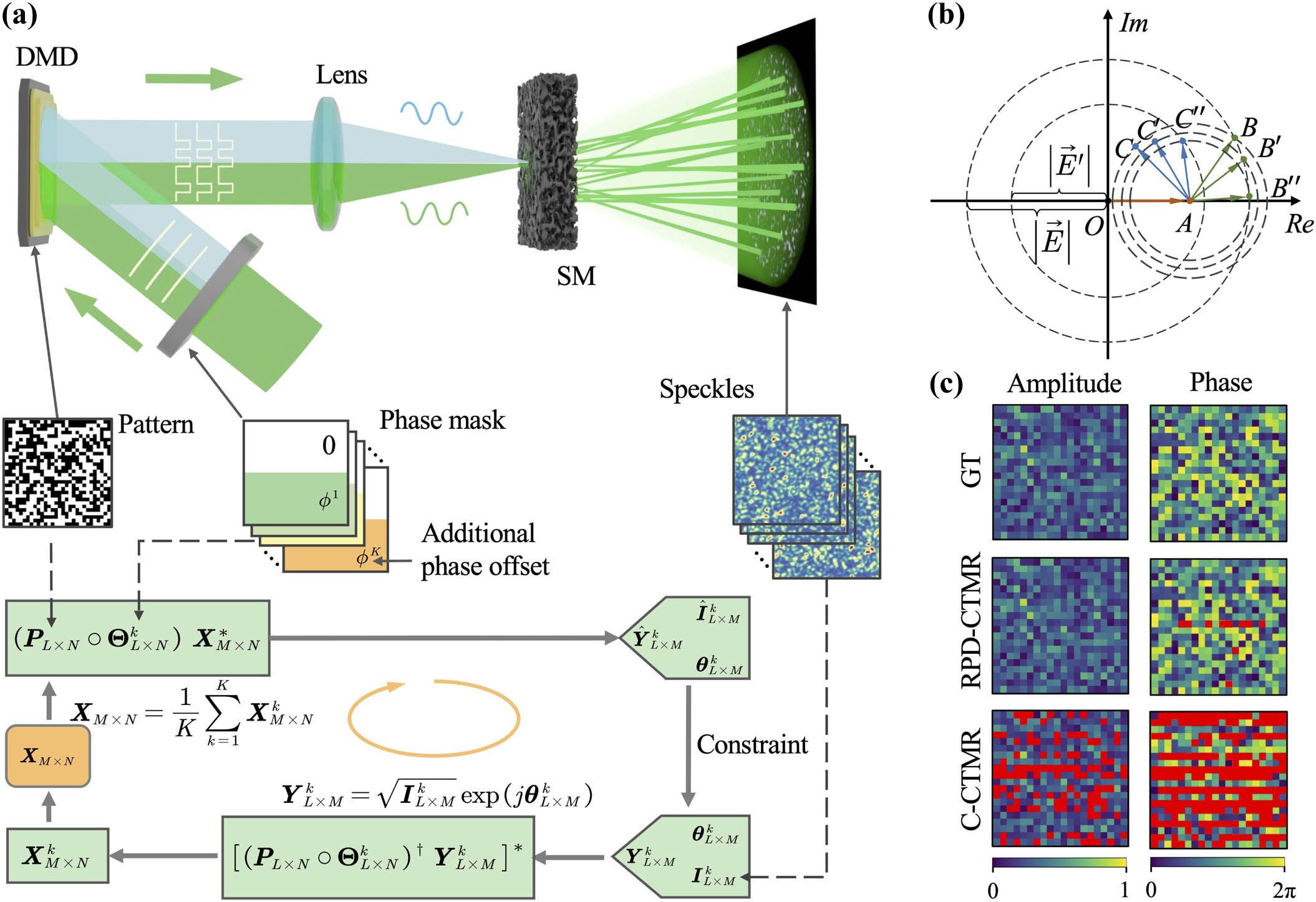
Figure 1(a) is the schematic of RPD-CTMR. A series of phase masks, , each possessing distinct regional phase factors, is performed on the probing fields modulated by the amplitude-type SLM, e.g., DMD. Here, represents the modulation modes of the DMD, and represents the dimension of phase masks. Consequently, each phase mask contributes to the generation of a distinctive speckle pattern. During each iterative phase of the phase retrieval algorithm, distinct CTMs are derived from the probing fields and their corresponding observed speckle patterns, each associated with different phase masks. The subsequent step involves computing the average of these CTMs, which is then utilized as the input for the subsequent iteration. The algorithm effectively accounts for the variations in the speckle patterns induced by the diverse phase masks and can mitigate any convergence ambiguities. As a result, the algorithm consistently gravitates towards a solution that much more accurately approximates the CTM of the SM compared to the conventional method.
Figure 1.Principle and schematic of RPD-CTMR. (a) Schematic of RPD-CTMR. (b) Illustration of phase constraint. . (c) Numerical simulations of CTM measurement via the RPD-CTMR and C-CTMR with equal to four. The top, middle, and bottom rows are the amplitude and phase distribution of ground truth (GT), and CTMs measured by RPD-CTMR and C-CTMR, respectively. The red pixels correspond to the CTM entries whose value deviates from the true value by more than 10%.
To generate the required probing fields for the RPD-CTMR, a binary random probing matrix is created. Here, we define , with the coefficient fine-tuned in accordance to match the experimental performance. The phase mask, , consists of two distinct regions: one introducing a phase offset to the probing field, and the other maintaining the phase of the probing field unaltered. Subsequently, under the phase mask , each row entry within the probing matrix is loaded onto the DMD generating distinct probing fields. For each probing field, different phase masks are sequentially applied to modulate it. After propagating through the SM, the distinct probing fields along with different phase masks will result in different speckle patterns, consistent with previous CTMR methods such as prVBEM [29], GS [34], and prVAMP [37]. The intensity of each speckle pattern is captured and integrated into a matrix . Then, the CTM of the SM, denoted as , could be solved from
Here, “” and “” represent the Hadamard product and conjugate transpose, respectively. is a matrix that repeats by times to match the dimensions mathematically.
In this work, we chose the GS algorithm as a phase retrieval algorithm [43]. The steps in one iteration involve the forward propagation, imposition of constraint, and backward propagation in each iteration utilizing the acquired information. The forward propagation generates an estimated observation matrix through the linear operation . With imposition of the constraint, the observation matrix is obtained, where is the phase of and is the intensity of the th speckle pattern. The backward propagation solves the CTM . Here, “” represents Moore–Penrose inverse. Finally, are averaged to update the CTM for the next iteration, until the solution converges to somewhere approximating to the real CTM.
Figure 1(b) illustrates the phase constraint of the RPD-CTMR. To facilitate the explanation, assume the CTM has only two entries, i.e., DMD has only two modulation modes, and the positions of and in the complex plane correspond to and in Fig. 1(b). Also, assume both modulation modes of DMD are turned ON, and as well as the amplitude of the output field is known. At this point, solving for is equivalent to finding a point on a circle with origin and radius . As shown in Fig. 1(b), , , and are all possible choices in this case, which indicates that the phase retrieval algorithm is highly susceptible to trapping in the local optimum in the absence of phase constraints. In comparison, if a probing field with a phase shift is generated to the second modulation mode of the DMD, the amplitude of output field would become . At this point, we could find that only and respectively satisfy as well as and respectively lie on the circles and observed in the two measurements. This simple example illustrates that with the additional phase constraint, the phase retrieval algorithm can avoid certain local optima and saddle points, and then easily converge to the global optimum.
3. RESULTS
A. Numerical Simulation
After reviewing the mechanism of RPD-CTMR, we numerically compared this method with a conventional CTMR method (C-CTMR), based on the GS algorithm as described in Refs. [34,37], in terms of measurement accuracy [Fig. 1(c)]. The numerical simulation was conducted on a GPU (GeForce GTX 1660 Ti, NVIDIA). We assumed the SM was random so that each entry within the CTM was independent and followed a circular Gaussian distribution [44]. Based on this, we set both the number of DMD modulations and camera pixels as 1024, and numerically generated the CTM with the dimensions of , which was taken as the ground truth (GT) for the following CTMR. Then, the light intensity at the th output channel would be [45]
Here, is the binary amplitude of the th modulation mode of the DMD, and corresponds to the phase shift at the th pixel of the phase mask . Hence, we emulated the probing field and resulting speckle pattern, including , , and , and then retrieved the CTM by the RPD-CTMR and C-CTMR methods at . Figure 1(c) displays the amplitude and phase distribution of the GT CTM , and CTMs and measured by RPD-CTMR and C-CTMR, respectively. To clearly compare these CTMs, we only show the values of pixels. The results show that the RPD-CTMR is robust and gives a higher CTM measurement accuracy in both amplitude and phase dimension.
To systematically verify the performance of RPD-CTMR, multiple numerical simulations were carried out (Fig. 2). We analyzed the normalized mean square error (NMSE) of 1024 rows in with the coefficient equal to 4 [Fig. 2(a)] and 12 [Fig. 2(b)]. The NMSE of the th row in the CTM was defined as . Here, “” denotes the -norm; denotes either the amplitude or phase of the optical field; and denote the th row of and the simulated GT , respectively.
Figure 2.Numerical simulation for comparison between the RPD-CTMR and C-CTMR. (a), (b) NMSE distribution of 1024 rows of with equal to (a) 4 and (b) 12. The NMSEs were calculated with respect to the amplitude, denoted by “”, and phase, denoted by “”. The subscripts R and C correspond to RPD-CTMR and C-CTMR, respectively. (c) Relation between the coefficient and TM measurement accuracy. The vertical coordinate of data points corresponds to the median of 1024 NMSEs. (d)–(f) Influence of the number of phase masks (d), phase shift between two consecutive masks (e), and the ratio between the areas of phase-shifted region and phase-preserved region in a phase mask (f) on the NMSE.
At equal to four, the constraint proved comparatively low for the C-CTMR, consequently leading to an NMSE exceeding 0.4, notably evident across the majority of rows in terms of both amplitude and phase [Fig. 2(a)]. In contrast, the RPD-CTMR maintained the NMSE below 0.1 under the same conditions. With an adjustment in to 12, both methods demonstrated a similar performance in terms of amplitude accuracy. However, the RPD-CTMR still maintained an advantage over the C-CTMR in the context of phase accuracy [Fig. 2(b)]. Our observations consistently indicated that the measurement accuracy of the RPD-CTMR surpassed that of the C-CTMR within the range of between 4 and 12 [Fig. 2(c)]. Notably, when exceeded 10, the RPD-CTMR exhibited the ability to achieve an amplitude and phase accuracy level of in the numerical simulations, surpassing the C-CTMR by three orders of magnitude. We further investigated the impact of various parameters on the CTM measurement accuracy of RPD-CTMR. Specifically, we analyzed the influence of the number of phase masks (). To achieve this, we need to specify the phase offset. In a nutshell, we chose to evenly distribute the phase offset across the range of zero to , i.e., . As shown in Fig. 2(d), the measurement accuracy was highest when and the phase offset was and . When , many stochastic constraints would be removed, while constraints with strong linear correlation would be introduced. This increases the complexity of solving the linear equation problem and results in reduced CTMR accuracy. At equal to two, we adjusted the value of to determine the optimal phase offset. Our result indicated that the optimal phase offset was or [Fig. 2(e)]. We also analyzed the ratio between the areas of phase-shifted region and phase-preserved region within a phase mask [Fig. 2(f)]. As a result, we found that the RPD-CTMR method achieved the optimal measurement accuracy when , and the phase mask was equally divided. The above simulation provides a theoretical basis for the parameter selection in the following experiment.
B. Experimental Setup and Characterization
We built a DMD-based RPD-CTMR system depicted in Fig. 3(a). To measure the CTM of the SM, a collimated beam originating from a 532 nm laser (Verdi G2, Coherent, Inc.) underwent expansion via a beam expander. The collimated beam was first modulated by a phase mask controller. The phase mask controller included a polarizing beam splitter (PBS251, Thorlabs Inc.), a controlled phase retarder (LCC1423-A, Thorlabs, Inc.), two half-circular customized aperture stops, two half-wave plates, and a beam splitter (BS004, Thorlabs Inc.). The polarized beam splitter effectively segregated the field into two distinct regions. One of these regions underwent an additional phase offset through the phase retarder. The customized aperture stops were integrated to regulate the illuminating area of the two beams and two half-wave plates were incorporated to ensure that both beams maintained identical polarization. Then, the two regions were merged into a unified beam using a beam splitter to apply the required phase mask on the incident beam. Consequently, the combined field was conjugated at the modulation surface of a DMD (JUOPT-DLP7000, JUOPT Technology Co., Ltd.). Then, we generated a probing matrix , where the specific values of and depended on different applications, and transferred each row of sequentially onto the DMD to modulate the probing fields. A stack of three diffusers (DG10-120, Thorlabs, Inc.) was used as the strong SM. The resultant speckle patterns were captured using a scientific complementary metal-oxide-semiconductor (sCMOS) camera (PCO.edge 5.5, PCO, Corp.) equipped with a objective lens. The CTM of this medium was extracted via both the proposed RPD-CTMR and C-CTMR methods, subsequently utilized in the context of the anti-scattering focusing and image transmission experiments. During the C-CTMR experiment, the phase retarder was deactivated to prevent the imposition of phase constraints on the probing fields. Subsequently, upon the acquisition of the CTM of the SM, all components except for a mirror were removed from the phase mask controller, enabling subsequent demonstrations, including those pertaining to anti-scattering focusing and image transmission.
Figure 3.Schematic and characterization of the RPD-CTMR system. (a) System setup. HWP, half-wave plate; AS, aperture stop; CAS, customized aperture stop; PBS, polarized beam splitter; BS, non-polarizing beam splitter; OL, objective lens. (b) Comparison between the recorded speckle pattern (denoted as GT) and estimated speckle patterns via RPD-CTMR and C-CTMR at equal to six. Scale bar: 150 µm. (c) Relative error distributions in the speckle patterns.
After the system setup, we measured the CTMs of the stacked diffusers through RPD-CTMR and C-CTMR, denoted as and , respectively. Both CTMs had the dimensions of , i.e., the number of camera pixels and DMD modulation modes , and the CTMs were measured with equal to six to reduce the impact of experimental noise. For the RPD-CTMR, we generated the probing matrix with the dimension of and . We set since we found this as the optimal value in the numerical simulation, and set the phase offset and . For the C-CTMR, the dimension of probing matrix was set to . Since each DMD pattern needed to be sequentially modulated by phase masks, the total number of measurements for RPD-CTMR was , which was the same amount as C-CTMR. To evaluate the CTM measurement accuracy, we estimated the speckle pattern using and , given the same probing field. Then, we compared these estimations with the GT speckle pattern captured by the camera. As depicted in Fig. 3(b), the RPD-CTMR estimation exhibited a higher correlation (0.84) with the GT, in contrast to the value (0.27) corresponding to the C-CTMR estimation. Further assessment involved the computation of the relative error between the estimation and the captured pattern, as illustrated in Fig. 3(c). The RPD-CTMR method demonstrated an improvement in estimation accuracy by a factor of 2.51 relative to the C-CTMR. These results confirm the superior accuracy of the RPD-CTMR in CTM measurement compared to the C-CTMR approach.
C. High-Contrast Anti-scattering Focusing
To demonstrate the practical applicability of the RPD-CTMR, we directed the beam for anti-scattering focusing against the stacked diffusers. Before anti-scattering focusing, we measured the CTMs, and , with dimensions of , utilizing both the RPD-CTMR and the C-CTMR, respectively. Subsequently, we computed the modulation pattern for focusing through the double phase retrieval method [29,37], then adjusting the incident field via the DMD in accordance with the modulation pattern. Figures 4(a) and 4(b) depict the intensity distributions and cross-section profiles of the resulting focal spots. Subsequent compensation for the scattering effects employing and yielded peak-to-background ratios (PBRs) of 123 and 35, respectively. Additionally, we designed a triangular pattern comprising nine spots, and successfully achieved multi-spot focusing through the diffusers [Figs. 4(c) and 4(d)]. Notably, in this multi-spot focusing experiment, compensating for the scattering effect using the RPD-CTMR led to a PBR of 16, marking a 3.6-fold increase compared to employing the C-CTMR. Furthermore, the relative deviation accounted for 4%, indicating a significant 10.2-fold enhancement compared to the utilization of C-CTMR.
Figure 4.Anti-scattering focusing. (a) Single-spot anti-scattering focusing using and . Scale bar: 100 µm. (b) Normalized cross-section profiles of focal spots along the white dashed lines in (a). (c) Multi-spot anti-scattering focusing using and . (d) Normalized cross-section profiles of focal spots along the white dashed lines in (c).
D. High-Fidelity Anti-scattering Image Transmission
Finally, we demonstrated the high-fidelity image transmission through the stacked diffusers with a CTM dimension of . In this demonstration, we loaded four distinct binary images, namely, the numeral “8,” smiley face, text “SJTU,” and random pattern, onto the DMD in four separate instances. These images were subsequently recovered from the corresponding speckle patterns using the double phase retrieval method, as illustrated in Fig. 5. Upon binarizing the images restored by RPD-CTMR, the bit error rate (BER) was effectively reduced to as low as 0.4%, representing a remarkable 24-fold improvement compared to the results restored by C-CTMR. These findings serve as compelling evidence that the RPD-CTMR excels in the precise measurement of CTM by effectively compensating for the detrimental scattering effects, thereby enabling superior image recovery capabilities in a scattering environment compared to the C-CTMR approach.
Figure 5.Anti-scattering image transmission. The first column shows the binary images to be transmitted through the SM. The second column shows the speckle patterns recorded by the camera. The two RPD-CTMR columns show the retrieved (left) and later binarized (right) images restored by . The two C-CTMR columns show the retrieved (left) and later binarized (right) images retrieved by . The values on the right side of the binary images represent their BERs.
We propose the concept of a high-accuracy RPD-CTMR measurement method to facilitate the performance of anti-scattering applications including anti-scattering focusing and image transmission. By applying external phase masks on the probing field and measuring the variation of the speckle patterns, the RPD-CTMR could impose proper constraints on the phase retrieval algorithm for the CTMR process and prevented the algorithm from being trapped in a suboptimal region. As a result, the solver consistently converged to a solution approximating the real CTM of SM. Since the RPD-CTMR method retrieves the CTM without preset conditions like Gaussian random distribution or a certain degree of sparsity, it is applicable to measure SM with an arbitrary scattering degree. Through the numerical simulation, we demonstrated that the RPD-CTMR method could give a more accurate CTM than the conventional method, given a particular . With the same number of observations, the RPD-CTMR method improved the CTM measurement accuracy by three orders of magnitude. We compared the performance of the RPD-CTMR and C-CTMR in the experiments of anti-scattering focusing and image transmission. The contrast of the focal spot was improved by a factor of 3.6 and the BER decreased by a factor of 24. The proposed RPD-CTMR method allows the adoption of SLMs without the phase modulation capability in the non-interferometric CTM measurement.
The RPD-CTMR still exhibits potential for enhancement. Particularly, there remains a scope for the further augmentation of the retrieved CTM dimension, which holds significant implications for various applications, notably in the domain of high-resolution biological optical imaging. Presently, our maximum retrievable dimension of the RPD-CTMR is constrained by the computational capabilities of our current computing platform. There are several approaches to mitigating this challenge. First, the enhancement of computing capabilities or the optimization of the efficacy of the phase retrieval algorithm could serve as viable solutions. This could involve replacing the GS algorithm with a more efficient alternative, such as the prVBEM, SDP, or EKF-MSSM, to expedite the CTMR process. Additionally, the utilization of more advanced GPUs could further support the high-dimension numerical computations. These concerted efforts would enable the utilization of a larger CTM featuring a heightened resolution, thereby facilitating more accurate compensation for the scattering effects. On the other hand, simplified modeling of the SM holds the potential to substantially reduce the number of entries within the CTM by several orders of magnitude. This approach would considerably expand the dimensions of the retrievable CTM. Consequently, the PBR of the anti-scattering focusing and the resolution of the anti-scattering transmitted image could be further enhanced.
Overall, the proposed RPD-CTMR method provides a new perspective to achieve high-accuracy CTM measurement using spatial light modulators without phase modulation capability. Our work is potentially useful in the applications such as biomedical imaging, optical communication, and optical computing.
[37] C. A. Metzler, M. K. Sharma, S. Nagesh. Coherent inverse scattering via transmission matrices: efficient phase retrieval algorithms and a public dataset. IEEE International Conference on Computational Photography (ICCP), 1-16(2017).
 AI Video Guide
  AI Picture Guide
 AI One Sentence