• High Power Laser Science and Engineering
  • Vol. 7, Issue 3, 03000e37 (2019)
M. Cerchez1、†, R. Prasad1, B. Aurand1, A. L. Giesecke1, S. Spickermann1, S. Brauckmann1, E. Aktan1, M. Swantusch1, M. Toncian2, T. Toncian2, and O. Willi1
Author Affiliations
  • 1Institut für Laser und Plasmaphysik, Heinrich-Heine-Universität Düsseldorf, 40225 Düsseldorf, Germany
  • 2Helmholtz-Zentrum Dresden-Rossendorf, 01328 Dresden, Germany
  • show less
    DOI: 10.1017/hpl.2019.21 Cite this Article Set citation alerts
    M. Cerchez, R. Prasad, B. Aurand, A. L. Giesecke, S. Spickermann, S. Brauckmann, E. Aktan, M. Swantusch, M. Toncian, T. Toncian, O. Willi. ARCTURUS laser: a versatile high-contrast, high-power multi-beam laser system[J]. High Power Laser Science and Engineering, 2019, 7(3): 03000e37 Copy Citation Text show less
    Schematic of the double-CPA architecture of the ARCTURUS laser system.
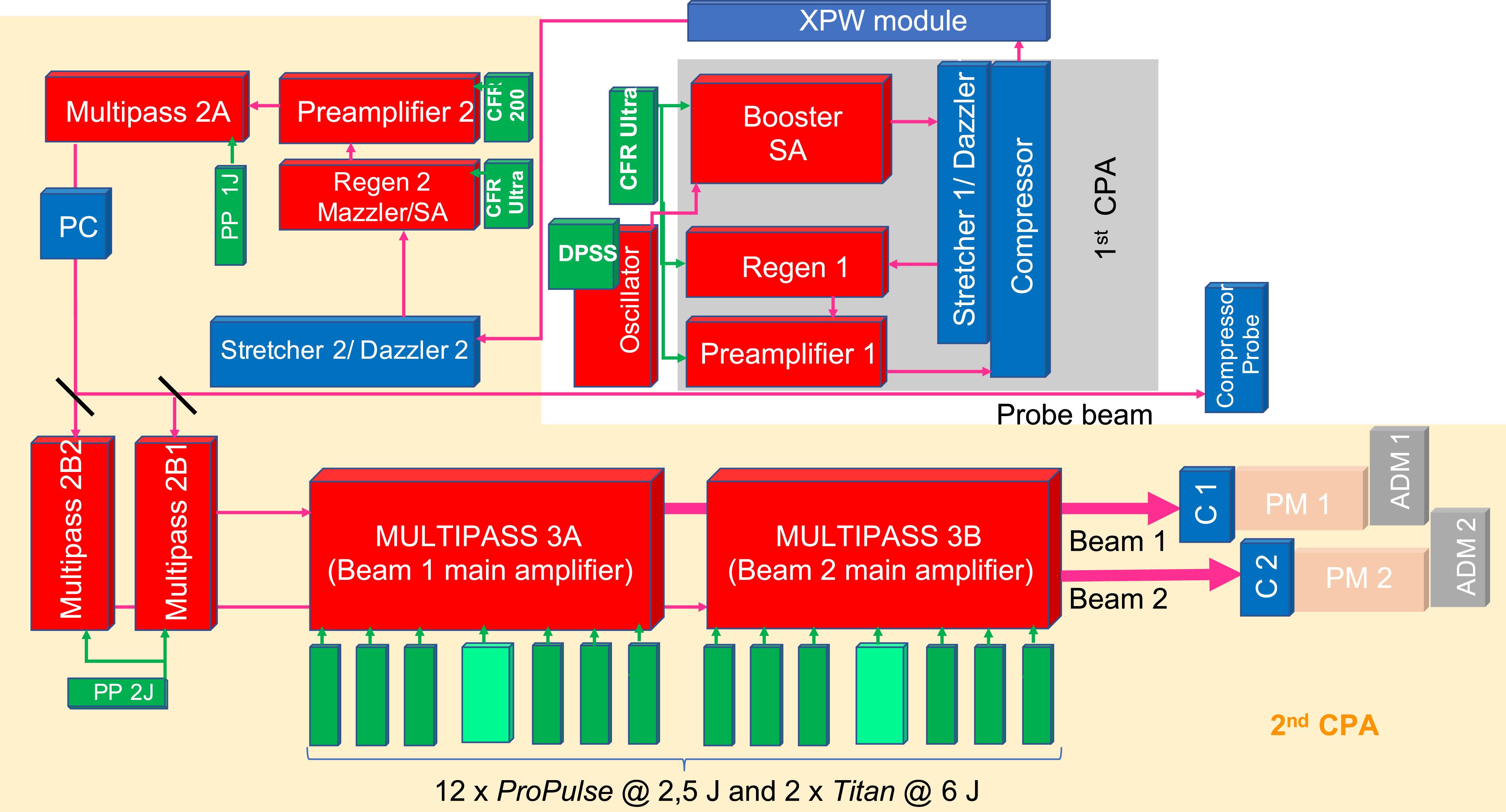
    Fig. 1. Schematic of the double-CPA architecture of the ARCTURUS laser system.
    SEQUOIA measurements of the ARCTURUS laser system showing the effect of different optical elements on the contrast improvement. The traces in (a) show the effect of the SA in the booster amplifier in a single-CPA configuration. In (b), a series of measurements indicates the influence of the XPW module and the effect of the regen 2 SA on the contrast enhancement in the double-CPA configuration. The traces in (c) show the present contrast quality for all three beams: both HP pulses (beam 1 and beam 2) and the probe beam.
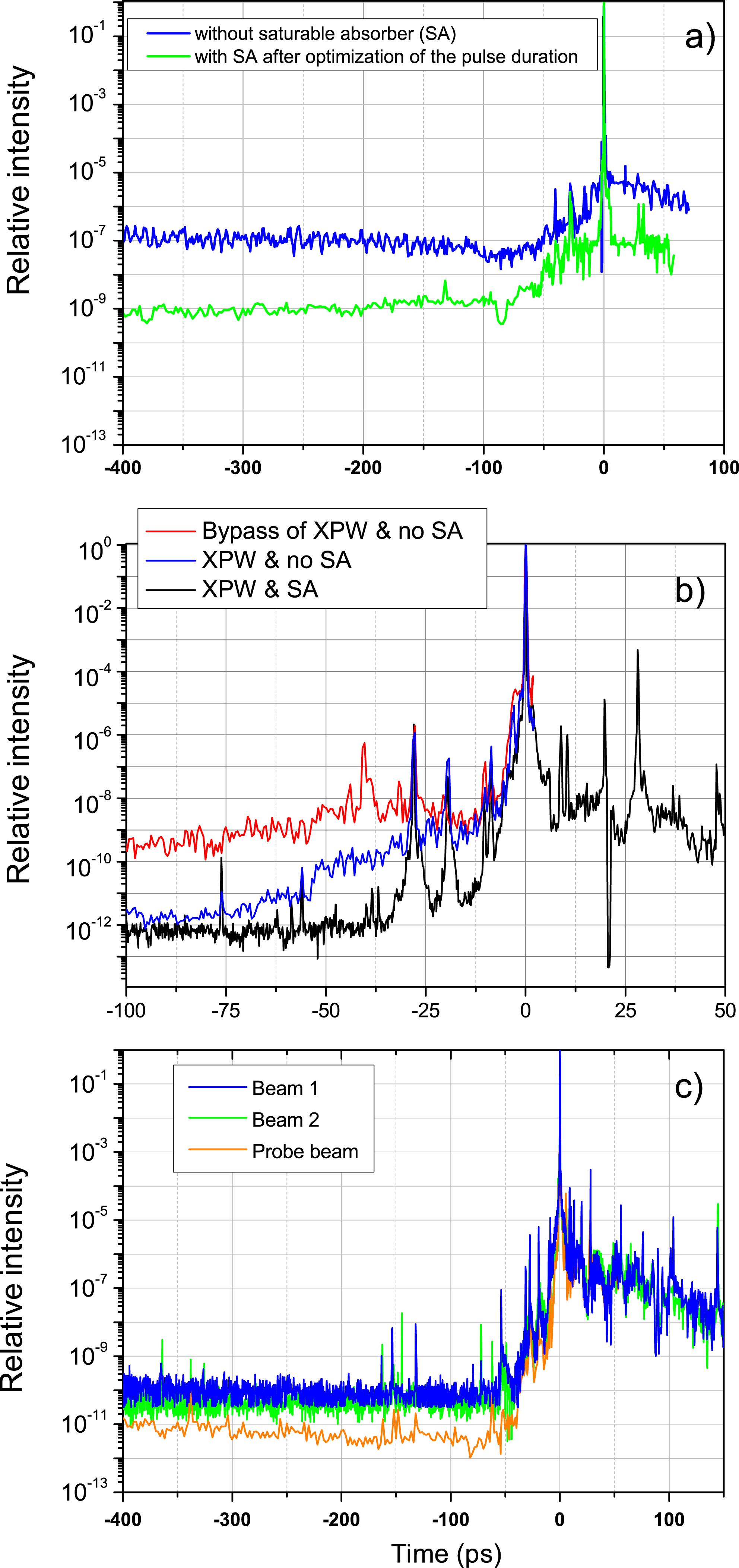
    Fig. 2. SEQUOIA measurements of the ARCTURUS laser system showing the effect of different optical elements on the contrast improvement. The traces in (a) show the effect of the SA in the booster amplifier in a single-CPA configuration. In (b), a series of measurements indicates the influence of the XPW module and the effect of the regen 2 SA on the contrast enhancement in the double-CPA configuration. The traces in (c) show the present contrast quality for all three beams: both HP pulses (beam 1 and beam 2) and the probe beam.
    (a) Wizzler measurements of the spectrum, spectral phase and (b) temporal profile close to the peak of the pulse for both HP beams after the compression, corresponding to the Dazzler configuration for the shortest pulse duration of beam 2. The compressor optical arrangement is drawn schematically in (c) and a picture of the vacuum probe compressor is shown in (d).
    Fig. 3. (a) Wizzler measurements of the spectrum, spectral phase and (b) temporal profile close to the peak of the pulse for both HP beams after the compression, corresponding to the Dazzler configuration for the shortest pulse duration of beam 2. The compressor optical arrangement is drawn schematically in (c) and a picture of the vacuum probe compressor is shown in (d).
    2D and 3D intensity distributions of beam 1 focused by an $F/2$ parabola at full energy (a), (b) without and (c), (d) with adaptive mirror correction. For comparison, the aberration-free, Rayleigh-limited focal spot size for the low-energy beam is shown in (e).
    Fig. 4. 2D and 3D intensity distributions of beam 1 focused by an $F/2$ parabola at full energy (a), (b) without and (c), (d) with adaptive mirror correction. For comparison, the aberration-free, Rayleigh-limited focal spot size for the low-energy beam is shown in (e).
    (a) Schematic of the plasma mirror at the ARCTURUS laser system. Two parabolas are used to focus the laser beam onto a multi-layer substrate and to recollimate it after the mirror. (b) Photo of the plasma mirror (PM) situated directly after the beam 1 compressor (CP1) of the ARCTURUS laser. Mirrors TM1 and TM2 can be driven out of the beam path so that the PM can be bypassed. (c) Transmission of the plasma mirror for different laser intensities at the PM substrate, from two series of measurements.
    Fig. 5. (a) Schematic of the plasma mirror at the ARCTURUS laser system. Two parabolas are used to focus the laser beam onto a multi-layer substrate and to recollimate it after the mirror. (b) Photo of the plasma mirror (PM) situated directly after the beam 1 compressor (CP1) of the ARCTURUS laser. Mirrors TM1 and TM2 can be driven out of the beam path so that the PM can be bypassed. (c) Transmission of the plasma mirror for different laser intensities at the PM substrate, from two series of measurements.
    SEQUOIA traces for the laser beam contrast with (blue) and without (black) the PM system inserted in the beam line. The red dashed line is the estimated contrast of the PM. The inset shows a detail of the temporal profile close to the main peak within the interval $\unicode[STIX]{x0394}t=[-20,10]~\text{ps}$.
    Fig. 6. SEQUOIA traces for the laser beam contrast with (blue) and without (black) the PM system inserted in the beam line. The red dashed line is the estimated contrast of the PM. The inset shows a detail of the temporal profile close to the main peak within the interval $\unicode[STIX]{x0394}t=[-20,10]~\text{ps}$.
    (a) Drawing of the shielded experimental hall. The main interaction beams, beam 1 (blue) and beam 2 (green), can be guided to the target chambers 1 and 2. In addition, beam 2 can be transported to a third chamber. The probe beam transport lines are shown in orange and guide the probe to any of the main chambers. The radiation shielding walls are marked in gray. (b) Pointing stability of focal spots of the HP beams 1 and 2 in target chamber 2 recorded over 20 consecutive shots.
    Fig. 7. (a) Drawing of the shielded experimental hall. The main interaction beams, beam 1 (blue) and beam 2 (green), can be guided to the target chambers 1 and 2. In addition, beam 2 can be transported to a third chamber. The probe beam transport lines are shown in orange and guide the probe to any of the main chambers. The radiation shielding walls are marked in gray. (b) Pointing stability of focal spots of the HP beams 1 and 2 in target chamber 2 recorded over 20 consecutive shots.
    Raw spectrum of the high-order harmonics generated by a laser-irradiated grating target of periodicity $\unicode[STIX]{x1D706}_{g}=410~\text{nm}$ and recorded in a single-shot mode by a flat-field XUV spectrometer. The laser was incident at $\unicode[STIX]{x1D703}=5^{\circ }$ onto the grating and the spectrometer was installed on the emission line at $\unicode[STIX]{x1D6FC}=5^{\circ }$ from the target surface. The lineouts were integrated over the CCD camera chip.
    Fig. 8. Raw spectrum of the high-order harmonics generated by a laser-irradiated grating target of periodicity $\unicode[STIX]{x1D706}_{g}=410~\text{nm}$ and recorded in a single-shot mode by a flat-field XUV spectrometer. The laser was incident at $\unicode[STIX]{x1D703}=5^{\circ }$ onto the grating and the spectrometer was installed on the emission line at $\unicode[STIX]{x1D6FC}=5^{\circ }$ from the target surface. The lineouts were integrated over the CCD camera chip.
    (a) Experimental setup of the frequency up-conversion of a laser beam ($2\unicode[STIX]{x1D714}_{L}$ scattered pulse) interacting with a high-energy electron bunch accelerated at the rear side of a thin foil by a high-intensity laser pulse ($\unicode[STIX]{x1D714}_{L}$ driver pulse). The electrons are detected by an electron spectrometer. A transmission grating in combination with an Andor camera is used as an X-ray diagnostic. (b) Image of the raw X-ray data obtained from a $27~\text{nm}$ DLC target shot, using the driver and the scattered beam simultaneously[43].
    Fig. 9. (a) Experimental setup of the frequency up-conversion of a laser beam ($2\unicode[STIX]{x1D714}_{L}$ scattered pulse) interacting with a high-energy electron bunch accelerated at the rear side of a thin foil by a high-intensity laser pulse ($\unicode[STIX]{x1D714}_{L}$ driver pulse). The electrons are detected by an electron spectrometer. A transmission grating in combination with an Andor camera is used as an X-ray diagnostic. (b) Image of the raw X-ray data obtained from a $27~\text{nm}$ DLC target shot, using the driver and the scattered beam simultaneously[43].
    Experimental setup for proton probing of a charge pulse. Two beams (probing beam and interaction beam) can be used to probe the interaction and to generate a charge pulse, respectively. The particular folding of the wire allows the observation of a larger field of view.
    Fig. 10. Experimental setup for proton probing of a charge pulse. Two beams (probing beam and interaction beam) can be used to probe the interaction and to generate a charge pulse, respectively. The particular folding of the wire allows the observation of a larger field of view.
    M. Cerchez, R. Prasad, B. Aurand, A. L. Giesecke, S. Spickermann, S. Brauckmann, E. Aktan, M. Swantusch, M. Toncian, T. Toncian, O. Willi. ARCTURUS laser: a versatile high-contrast, high-power multi-beam laser system[J]. High Power Laser Science and Engineering, 2019, 7(3): 03000e37
    Download Citation