• High Power Laser Science and Engineering
  • Vol. 7, Issue 3, 03000e37 (2019)
M. Cerchez1、†, R. Prasad1, B. Aurand1, A. L. Giesecke1, S. Spickermann1, S. Brauckmann1, E. Aktan1, M. Swantusch1, M. Toncian2, T. Toncian2, and O. Willi1
Author Affiliations
  • 1Institut für Laser und Plasmaphysik, Heinrich-Heine-Universität Düsseldorf, 40225 Düsseldorf, Germany
  • 2Helmholtz-Zentrum Dresden-Rossendorf, 01328 Dresden, Germany
  • show less
    DOI: 10.1017/hpl.2019.21 Cite this Article Set citation alerts
    M. Cerchez, R. Prasad, B. Aurand, A. L. Giesecke, S. Spickermann, S. Brauckmann, E. Aktan, M. Swantusch, M. Toncian, T. Toncian, O. Willi. ARCTURUS laser: a versatile high-contrast, high-power multi-beam laser system[J]. High Power Laser Science and Engineering, 2019, 7(3): 03000e37 Copy Citation Text show less

    Abstract

    With the latest configuration, the Ti:Sa laser system ARCTURUS (Düsseldorf University, Germany) operates with a double-chirped pulse amplification (CPA) architecture delivering pulses with an energy of 7 J before compression in each of the two high-power beams. By the implementation of a plasma mirror system, the intrinsic laser contrast is enhanced up to $10^{-12}$ on a time scale of hundreds of picoseconds, before the main peak. The laser system has been used in various configurations for advanced experiments and different studies have been carried out employing the high-power laser beams as a single, high-intensity interaction beam ($I\approx 10^{20}~\text{W}/\text{cm}^{2}$), in dual- and multi-beam configurations or in a pump–probe arrangement.

    1 Introduction

    The generation of multi-terawatt, sub-picosecond laser pulses was until recently only possible at large facilities due to the major infrastructure and personnel demands. However, in the past decade, the Ti:Sa laser technology, delivering hundreds of terawatts, has become commercially available. Owing to the short laser pulse lengths (tens of femtoseconds), the energy requirements are thus kept at the level of a few joules, making the infrastructure and personnel demands affordable and attractive at an university-scale laboratory. The combination of ultrashort pulse duration and the high peak power achieved nowadays[1] have opened up unique opportunities for the study of fundamental physical processes in the relativistic regime[24]. Various plasma conditions have been explored, aimed at improved physical parameters for laser-driven particle acceleration or the generation of coherent radiation required for different applications. Recently, novel interaction conditions and unique plasma states have been created and controlled by the combined effects of multiple beams interacting with a target sample[58]. In the past, experiments which intended to explore the potential of a dual-beam configuration for plasma investigations or for probing the main interaction relied on a single high-power (HP) beam used in a split-off configuration. Although the two pulses which originate from the same beam are temporally synchronized, there are limitations on each pulse energy, duration and focus quality[9, 10]. The large infrastructure, multi-petawatt-class laser facilities[11] presently being built are designed on multiple beam architectures (e.g. APOLLON, France[12]; Extreme Light Infrastructure[1315]; SULF, China[16]).

    In this paper we present the up-to-date, multi-beam architecture of the ARCTURUS laser facility and the operational physical parameters of the laser beams. The interaction of the pulses with solid, cluster and gaseous targets was extensively investigated and a brief overview of the recent experimental studies performed in either a single- or multi-beam configuration is presented. The great versatility of the laser system is shown by the different experimental configurations used for various interaction conditions.

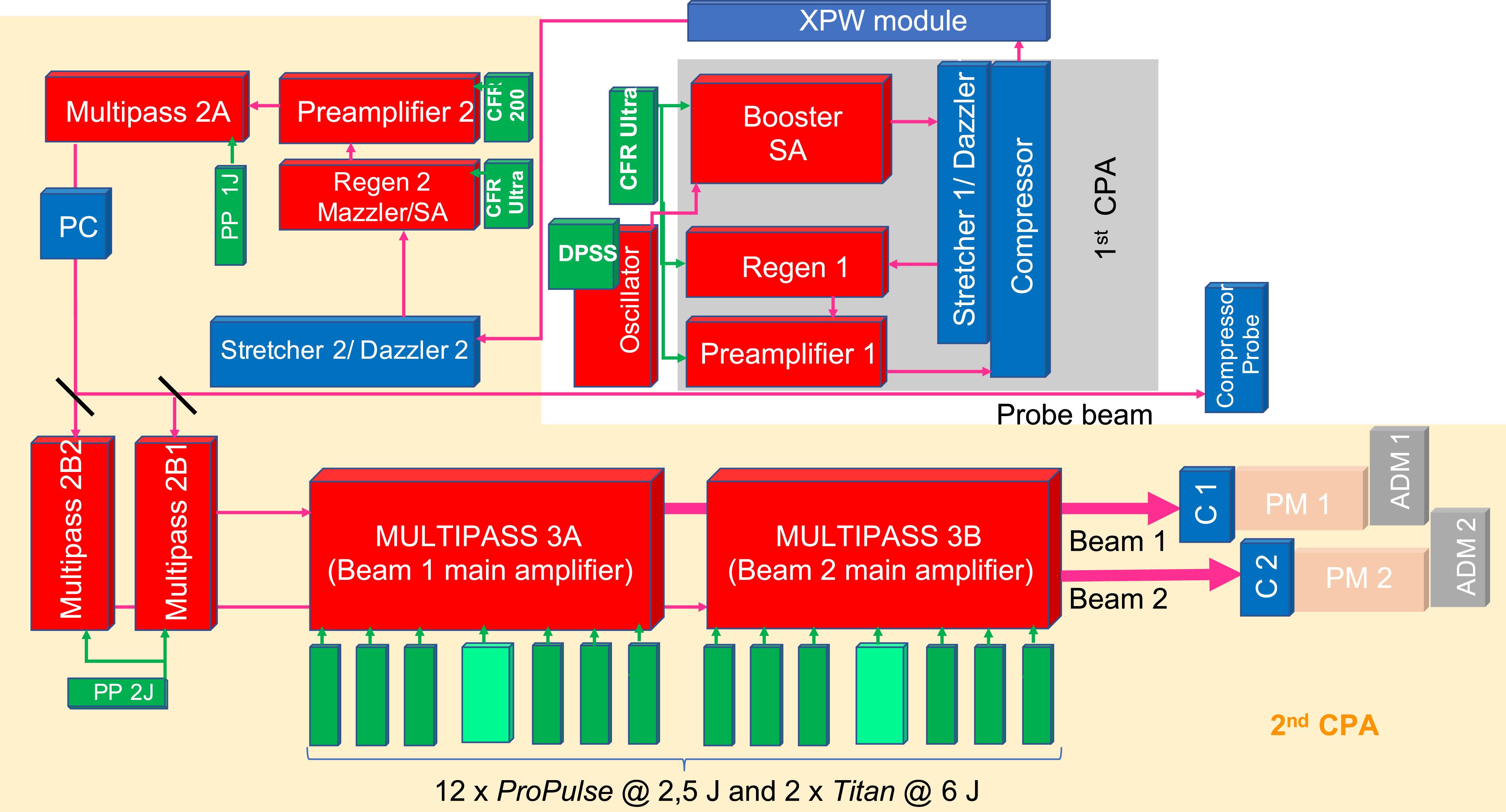
    2 Double-CPA architecture of the ARCTURUS laser system

    The ARCTURUS laser facility located at the University of Düsseldorf, Germany is a university-based laser laboratory dedicated to the study of the interactions of high-power, high-contrast laser pulses with matter at intensities which can exceed $10^{20}~\text{W}/\text{cm}^{2}$. The laser system originates from a commercial $100~\text{TW}$ Ti:Sa laser system[17] designed and manufactured by Amplitude Technologies[18] on a modular design, based on the so-called ‘chirped pulse amplification’ (CPA) scheme[19]. The laser system has been the subject of three major upgrades in the past decade, aimed at the installation of a second HP beam, contrast improvement and peak energy enhancement. The facility operates at present at a repetition rate of $5~\text{Hz}$ with two HP interaction beams, each beam having an energy of $7~\text{J}$ before compression and a probe pulse of $3~\text{TW}$ power, all pulses being separately compressed to about $30~\text{fs}$. The present laser architecture is based on a double-CPA configuration connected by an nonlinear temporal filter based on cross-polarized wave generation (XPW module)[20]. The schematic of the laser amplification chain is shown in Figure 1.

    2.1 First CPA module

    The seed pulse originates from a commercial Ti:Sa oscillator pumped by a CW diode pumped solid state laser (DPSS) which delivers sub-20 fs, 5 nJ pulses with a spectral bandwidth of about $100~\text{nm}$ at a repetition rate of $76~\text{MHz}$. The seed is injected into a so-called Superbooster module, which consists of the first CPA stage and the XPW module. The first CPA unit includes a contrast ratio booster, where the pulse is amplified up to the $\unicode[STIX]{x03BC}\text{J}$ level in a 14-pass amplifier with a gain of about $10^{4}$ and pumped by the second harmonic radiation of a Nd:YAG pump laser (CFR Ultra by Quantel). The pulse repetition rate is reduced to $10~\text{Hz}$ and the amplified spontaneous emission (ASE) contrast is cleaned by a saturable absorber. Further, the pulse is stretched optically to about $500~\text{ps}$ by an Öffner-type stretcher[21, 22] with a design based on an all-reflective triplet combination, including a concentric concave and a convex spherical mirror system and a grating placed in the plane of the center of curvature. Hence, the optical arrangement ensures low-aberration operation, as the reflective optics reduces the chromatic aberration and the opposite signs of the mirrors’ radii of curvature cancel the spherical aberration and the astigmatism. As the first grating is placed on-axis, the coma is avoided[21, 22]. The stretcher efficiency is about $20\%$. An acousto-optic programmable dispersive filter (AOPDF) (Dazzler by Fastlite)[23] is inserted in the path of the beam to pre-compensate the spectral phase. Further, the pulse is amplified by two amplification stages, consisting of a regenerative amplifier and a multi-pass ‘butterfly’ amplifier. The regenerative amplifier generates about $800~\unicode[STIX]{x03BC}\text{J}$ at 10 Hz and includes two Pockels cells in order to optimize the contrast ratio. After the multi-pass amplifier, the pulses reach about $3~\text{mJ}$ in energy. At the end of the first CPA stage, the pulse is temporally re-compressed to approximately $40~\text{fs}$ (Fourier limited) pulse duration in a double-pass compressor grating. Due to gain narrowing, the spectral bandwidth at the end of the first CPA stage is $35~\text{nm}$.

    In the ARCTURUS laser chain, the laser contrast is improved by two main stages. Firstly, at the front end of the laser system, the contrast is controlled by saturable absorbers, Pockels cells and, recently, by an XPW module. Most of temporal profile quality of the output pulses is defined at this stage. The second contrast improvement is achieved by a single plasma mirror system, which can be inserted in each of the main beam paths after the compressor.

    Before the XPW module implementation, the intrinsic laser contrast was limited by the regenerative amplifier to ${\sim}3\times 10^{-7}$ at $12~\text{ns}$ (the regen roundtrip) and it could be improved up to $6\times 10^{-8}$ when a saturable absorber (SA) was inserted after the regenerative cavity. For the configuration when the SAs were present in both the regen and booster amplifiers, the contrast on a $400~\text{ps}$ time scale before the pulse peak was measured with a SEQUOIA third-order auto-correlator; the recorded temporal profile is shown in Figure 2(a) as the green trace. On the time axis, negative values correspond to the time interval prior to the peak of the main laser pulse. For comparison, the blue trace shows the temporal profile obtained in a configuration when the SA from the booster amplifier was bypassed.

    2.2 Cross-polarized wave filter

    The XPW module is based on the third-order nonlinear effect of cross-polarized wave generation (XPW) in a $\text{BaF}_{2}$ crystal[24]. In the module, the compressed pulse with an energy of about $1~\text{mJ}$ is focused with a high-$F$-number lens through a hollow fiber for spatial filtering onto the XPW-crystal placed in an evacuated tube. From the incoming linearly polarized wave, a wave of the same frequency, but with a perpendicular polarization, is created. Hereby, the intensity of the cross-polarized wave is proportional to the third power of the input intensity and, thus, the pulse pedestal can be drastically reduced. One should note that the XPW module is placed between a pair of polarizers and the temporal contrast performance is limited by the extinction ratio of the polarizing elements. With the XPW module, the contrast ratio in the case of our laser system is improved by three orders of magnitude, with an efficiency of about $10\%$, and the pulse spectrum is broadened by a factor ${\sim}1.7$ to about $60~\text{nm}$[20].

    The contribution of the XPW module to the beam temporal profile was studied. In the double-CPA architecture, the laser pulse was firstly temporally characterized by bypassing the XPW module and removing the SA after regen 2, in the so-called low-contrast configuration (red trace in Figure 2(b)). In this case, the ASE contrast was better than $10^{-9}$ at $100~\text{ps}$ and around $10^{-8}$ at $10~\text{ps}$, while at $1~\text{ps}$ before the laser pulse maximum, the contrast was $10^{-4}$. After the first CPA unit, the beam was guided through the XPW module and the ASE contrast for hundreds of picoseconds before the peak was improved by three orders of magnitude to $10^{-12}$ (blue trace). For this measurement, in the time interval between $-75$ and $-15$  ps, the efficiency of the pedestal cleaning decreases, resulting in a drop in contrast from $10^{-12}$ to $10^{-8}$. By additionally inserting the SA after the regen 2, the temporal profile improves to $10^{-12}$ at about $40~\text{ps}$ before the main pulse, while the rising edge of the pulse ramps up by five orders of magnitude, from $10^{-11}$ at $-20~\text{ps}$ to $10^{-6}$ at $-1~\text{ps}$. The peaks measured at about $-30~\text{ps}$, $-20~\text{ps}$ and $-10~\text{ps}$ are artifacts of the postpulses on the SEQUOIA measurements, as one can see on the traces after the peak. Summarizing the effects of the SAs and XPW module, the ASE level is improved by three orders of magnitude compared to the low-contrast configuration and by five orders compared to the low-contrast case before the upgrade (red trace in Figure 2(b) and blue trace in Figure 2(a), respectively). In Figure 2(c) the temporal profiles of both main HP beams (beam 1 and beam 2) and of the probe beam are shown for comparison.

    2.3 Main amplification stage

    After the XPW module, the pulse is recollimated and further seeded in a second CPA module where the pulse is again stretched optically by another Öffner-type stretcher to $10~\text{ps}/\text{nm}$ bandwidth and the spectral phase is once more compensated by an additional acousto-optic modulator (Dazzler) inserted in the beam path. Similarly as in the Superbooster module, the pulse is injected in a regenerative cavity with a Pockels cell and is amplified to the millijoule energy level. A second acousto-optical modulator (Mazzler by Fastlite) is installed into the regenerative cavity, increasing the spectral bandwidth to $80~\text{nm}$ to compensate for the effects of gain narrowing in the high-gain regenerative amplifier (of about $32~\text{nm}$). Two low-gain, four-pass amplifiers (preamplifier II with a gain of 30 and 2A amplifier with a gain of 10) are employed to increase the pulse energy level to $300~\text{mJ}$. The amplifiers are pumped by frequency-doubled Nd:YAG lasers, a CFR 200 (Quantel, $150~\text{mJ}$) and an Amplitude Technologies Pro-Pulse ($900~\text{mJ}$), respectively. The last pump laser as well as all other Pro-Pulse pumps operates at $5~\text{Hz}$.

    At this point, the pulse is cleaned by a large-aperture (1 inch, 1 inch $=$ 2.54 cm) Pockels cell and further split with a 30:35:35 ratio into three beams. The $30\%$ fraction represents the probe beam, and is guided by a delay line setup into a vacuum compressor. The other two $35\%$ fraction beams are injected into two identical four-pass amplifiers (2B1 and 2B2) pumped by a Pro-Pulse ($900~\text{mJ}$ per amplifier) with a gain factor of 20, where the pulses reach $400~\text{mJ}$ in energy. The main amplifiers (3A and 3B) are large-scale, four-pass amplifiers where the beams with a diameter of $3.5~\text{cm}$ are amplified up to $7~\text{J}$. The main Ti:Sa crystal of $5~\text{cm}\times 5~\text{cm}\times 3~\text{cm}$ in size is cryogenically cooled to prevent thermal lensing. The total pumping energy of each of the two large amplifiers is $21~\text{J}$ at the crystal, provided by six Pro-Pulse pump lasers of $2.5~\text{J}$ energy each and a Titan Amplitude Technologies pump laser of $6~\text{J}$. Before exiting the amplifier, the laser beams are finally expanded and collimated by a 3$\times$ transmission telescope to about 10 cm in diameter ($1/e^{2}$).

    2.4 Spectral and spatial phase compensation: compressors and adaptive optics

    All three beam lines have independent delay lines and can be separately compressed by double-pass optical compressors on a four-grating and rooftop mirror arrangement. In order to keep the vacuum compressor chamber and the grating size as small as possible, the compressors have a compact geometry, with the optical path of the stretched pulse folded in two parallel planes on top of each other[25, 26]. The stretched pulse is firstly incident and dispersed by a first pair of gratings (1 and 2) and then reflected by a rooftop mirror to the second plane of the optical path which contains the gratings 3 and 4, where the pulse passes in the reverse direction. Hence, the red part of the stretched pulse travels a longer distance than the blue part, a negative dispersion is induced, and consequently, the pulse is compressed. The gratings are gold coated with a grating constant of $g=1.48~\unicode[STIX]{x03BC}\text{m}^{-1}$ and dimensions $135~\text{mm}\times 175~\text{mm}\times 30~\text{mm}$ (1 and 4) and $135~\text{mm}\times 230~\text{mm}\times 30~\text{mm}$ (2 and 3). A schematic of the optical arrangement of the compressor is shown in Figure 3(c) while a picture of the probe compressor is shown in Figure 3(d). The compressors’ efficiency is in the range 60%–70%. The pulse length and spectral phase can be monitored online by a SPIDER diagnostic[27] or Wizzler measurement[28]; for the optimization of the pulse duration and best temporal performance, the measured spectral phase is fed into a closed-loop algorithm which allows optimization of the Dazzler correction before the regenerative amplifier 2. With the same Dazzler configuration it is possible to manage the correction for the three compressors such that all three pulses can be compressed to about $30~\text{fs}$. In the case that one of the beams is optimized to about $25~\text{fs}$, the other two beams can be compressed to about $35~\text{fs}$ (Figures 3(a) and 3(b)). In order to limit the vibrations induced by the vacuum system on the optical setup, the compressor table is directly fixed to the laser hall’s floor and separated by vacuum feedthroughs from the compressor’s housing. This technical solution leads to a greater stability of the compressor alignment, and consequently of the pulse temporal characteristics.

    For the highest intensity possible on the target, an aberration-free wavefront which defines the quality of the laser beam focus is important. Essentially, the main contribution to the wavefront distortion originates from the main amplification stage, due to thermal lensing and birefringence effects. The 2D and 3D far-field intensity distributions of the beam 1 at full energy are shown in Figures 4(a) and 4(b), respectively, where severe distortions of the beam focus are observed in the case of the high-energy beam. For comparison, the intensity distribution of the same beam in the low-energy case (without the amplification in the 2A, 2B1 and 3A modules) is shown in Figure 4(e). Consequently, a closed-loop adaptive optical system[29] aiming to correct the low-order aberrations can be included in each of the beam lines after the compressor. The system consists of an adaptive deformable bimorph dielectric-coated mirror (ADM) with 32 elements[29] and a Hartmann–Shack sensor. Firstly, the spatial phase is evaluated by the sensor and the required correction is calculated and applied by the ADM within a closed-loop algorithm. The effect of the wavefront correction applied by the ADM is visible on the quality of the focal spot, which contains $50\%$ energy in a focal spot $2.6~\unicode[STIX]{x03BC}\text{m}$ in diameter, i.e., close to the diffraction limit (Figures 4(c) and 4(d)). Different filtering levels were used in front of the camera to record the distributions in Figures 4(a), 4(b) and 4(e); thus, one cannot make a direct comparison between the maximum intensity values of each distribution.

    2.5 Plasma mirror system

    A further contrast enhancement can be achieved by means of a plasma mirror (PM)[30, 31]. The operating principle of PM is illustrated in Figure 5(a). The laser pulse is focused to a spot of about $50~\unicode[STIX]{x03BC}\text{m}$ (FWHM) in diameter onto a coated glass substrate, so that the pre-pulses and the ASE pedestal are still transmitted, while the rising edge of the main pulse is able to ignite an overdense plasma reflecting the main pulse. In this way, the PM acts as a switch with a femtosecond response time and the contrast can be effectively improved close to the peak of the pulse. Antireflection-coated substrates are used to improve the temporal contrast ratio of terawatt laser systems substantially.

    At the ARCTURUS laser system, two identical PM setups are installed in the HP beam lines. A picture of the PM installed in beam line 1 is shown in Figure 5(b). The design of the PMs was fitted to the ARCTURUS laser parameters, such as pulse duration, intensity and space limitation in the laser room[32]. While the XPW module is part of the core design of the laser architecture, the PM system acts as an inserted module and can be used according to the experimental requirements. One major advantage of the PM is that the laser system itself does not require significant changes, the input power is principally not limited, and it can be bypassed without modifying the beam parameters (except the contrast and energy). After the compressor, the pulse is injected into the PM setup by a turning mirror and focused onto an antireflective multi-layer-coated substrate with an intensity of about $10^{16}~\text{W}/\text{cm}^{2}$ by an off-axis parabolic mirror with a focusing number $F/22$. At this intensity, the generated plasma has a reflectivity of about $80\%$. The dependence of the PM reflectivity over the intensity range between $10^{16}~\text{W}/\text{cm}^{2}$ and $10^{17}~\text{W}/\text{cm}^{2}$ was recorded by moving the substrate along the focal axis (the results are shown in Figure 5(c)). The operating performance of the PM relies on the substrate coating, which can be used uncoated with $4\%$ Fresnel reflectivity or coated with a single- or multi-layer antireflective coating (Eskma Optics). In case of the multi-layer, the maximum reflectivity of the ‘cold’ substrate specified by the company is about 0.1%–0.2% over the range 750–850 nm. Thus, a contrast improvement in the low-intensity regime is expected to reach theoretically three orders of magnitude. However, a smaller value of the contrast improvement was observed for high-power conditions, as discussed later in the text. After every shot, the substrate is moved to a fresh surface position. More details about the PM setup and characterization of the ARCTURUS system can be found in Ref. [33].

    The contrast performance of the PM substrate has been investigated and the temporal profiles with and without the PM system included in the beam path are shown in Figure 6. The data shown here have been recorded without the XPW module, and the SEQUOIA trace shows a contrast of the laser pulse of about $10^{-9}$ at delays greater than $-200~\text{ps}$, while the contrast degrades to $10^{-7}$ at $-10~\text{ps}$ (black trace). The recording of the pulse temporal profile after interacting with the PM substrate poses a few difficulties. The pulse energy must be a compromise between the level required to create a plasma at the substrate and ensure the SEQUOIA operates in the full dynamic range, while at the same time avoiding pulse distortion due to nonlinear effects (for instance, self-phase modulation) at the outcoupling window used during the measurement. Consequently, the measurements were limited by obtaining the most important part of the trace, namely around the main peak and at the ASE level. The measurement shows a contrast enhancement up to two orders of magnitude (blue trace), while the estimated value of the contrast improvement is indicated by the dashed red line. The contrast profile shortly before the main pulse is shown in the inset of Figure 6. The temporal contrast at $-6.6~\text{ps}$ is improved from $10^{-7}$ to $10^{-9}$. Also, the pulse wings are strongly reduced. The PM triggers at about $-1~\text{ps}$ before the main pulse, where the difference between the black and the blue curves becomes negligible.

    The high contrast of the interaction beams is of key importance for experiments employing thin foils of nanometer thickness, nano-structured targets, or randomly or periodically modulated surfaces (gratings), preventing the laser pedestal and its rising edge from destroying the target or the surface modulations prior to the arrival of the peak of the pulse[3437]. As experimentally demonstrated in Figure 6, the PM system is able to improve the contrast by at least two orders of magnitude in the case of a multi-layer antireflection-coated substrate, but intermediate contrast values are achievable as well if an uncoated PM substrate is used instead. Thus, depending on the experimental requirements, the contrast can be independently varied over two orders of magnitude for each beam[34].

    The damaged area created on the PM substrate acts as on optical isolator for the laser energy backscattered from the interaction region, as the reflectivity of the damaged spot on the PM substrate is very low compared with the PM reflectivity in the operational mode. One may note that the interaction area is located about $10~\text{m}$ from the PM and the back-reflected beam fraction interacts with a highly scattering impact spot of about $2~\text{mm}$ diameter and of very low specular reflectivity. Thus, in experiments using a counter-propagating geometry, PM systems can prevent potential damage in the laser chain.

    3 Versatility of laser parameters in the experimental area and online diagnostics

    The amplified, compressed and temporally shaped beams are directed through separate vacuum beam lines to the experimental area, which is a radiation-shielded hall (Figure 7(a)). The energy throughput of the beam lines combined with the compressor efficiency is in the region of $50\%$, while this percentage drops to about $40\%$ when the PM system is inserted in the beam line. In the bunker, two main interaction chambers can accommodate the coupling of all three beams, while a smaller chamber (dedicated mostly for experiments relevant to medical applications) is only designed for one of the main beams.

    The laser architecture allows a flexible selection of the parameters of the beams. In the operation regime without the PM, the beams’ energy can be adjusted by controlling the amplification level. In the interaction area, the energy is typically in the range 1–3 J, but it can be lowered to the millijoule level, depending on the experimental requirements. The beam energy can be reduced in fine steps by employing an attenuator assembly consisting of a large-aperture waveplate and two thin-film polarizers. By means of different focusing optics and geometries, the interaction beams can irradiate the targets at an intensity which can range from the highest achievable $5\times 10^{20}~\text{W}/\text{cm}^{2}$ down to $10^{16}~\text{W}/\text{cm}^{2}$. Note the beam transport lines shown in Figure 7(a) have a modular structure and allow a flexible reconfiguration of the beams’ injection into the chambers, depending on the experimental requirements and conditions (e.g. preferential orientation of the diagnostics, restricted radiation safety conditions, and large-scale vacuum equipment).

    A number of complex experiments based on a counter-propagating geometry (e.g. Thomson scattering, pulse amplification by stimulated Brillouin scattering, studies of radiation reaction and strong field quantum electrodynamics (QED) effects, and counter-propagating shocks dynamics)[38, 39] can pose significant experimental difficulties and potential risks for the optical components in the laser chain, as a radiation leak of one of the beams can couple to the amplification line of the other beam. Assessed on the ARCTURUS architecture, a laser leak or back reflections can reach the main Ti:Sa crystals within the amplification time window, with unpredictable consequences and a high risk of damage, as the beam remnant properties (collimation, energy, etc.) are unknown. As mentioned before, the PM as an optical isolator ensures safe operation even in a counter-propagation configuration. Moreover, other angular orientations of the main beams are possible, starting from $45^{\circ }$ (limited by the adjacent positions of the off-axis parabolas) up to $180^{\circ }$. Collinear propagation ($0^{\circ }$) of one of the main beams and the probe beam is possible by employing an off-axis parabola with a $0.5^{\prime \prime }$ central hole for the probe injection. While in normal operation conditions, the main pulses are p-polarized, large-aperture waveplates can change the polarization to s- or circular (possible for each beam independently). In the interaction area, the main beams can be converted to $2\unicode[STIX]{x1D714}_{L}$ by KDP crystals of $3~\text{inch}$ diameter and $100~\unicode[STIX]{x03BC}\text{m}$ thickness with an efficiency between 10% and 20%.

    The synchronization of the pulses in the interaction area relies only on the optical path compensation, as all three beams originate from the same front end. The relative delays between the main interaction pulses can be varied in the range $\pm 3~\text{ns}$ in $10~\text{fs}$ steps by high-precision translation stages. The synchronization and the spatial overlap of the interaction beams on the target are monitored by optical methods (interferometry and/or shadowgraphy). A spatial variation of the focal spot in the range $5{-}10~\unicode[STIX]{x03BC}\text{m}$ (Figure 7(b)) was measured, while a temporal uncertainty of $300~\text{fs}$ in the beams’ synchronization was found. Similarly, the arrival of the probe pulse can be temporally adjusted relatively to the main interaction beams by a number of delay stages.

    In addition, the pulse duration can be varied from the optimized compressed pulse corresponding to the shortest duration of about $\unicode[STIX]{x1D70F}_{op}=30~\text{fs}$, to a few tens to hundreds of picoseconds (chirped) by detuning the gratings of the compressor, or even bypassing the compression stage. In case of the chirped pulse, the operation of the PM poses a few limitations in terms of the input energy and pulse duration, as an intensity level of $10^{16}~\text{W}/\text{cm}^{2}$ has to be obtained. Even pulses of up to $3~\text{ps}$ duration were temporally cleaned by the PM system in several experiments. Also, positive or negative chirped pulses can be created with a chirp factor $\unicode[STIX]{x1D6FC}=(2\unicode[STIX]{x1D714}_{L}^{2}\unicode[STIX]{x1D70F}_{op}\unicode[STIX]{x1D70F}_{st})^{-1}=2\times 10^{-5}{-}10^{-6}$ for pulses stretched to a duration of $\unicode[STIX]{x1D70F}_{st}=3~\text{ps}$.

    The versatility of the laser parameters generated by the ARCTURUS system can be exploited in a wide variety of experimental studies. Therefore, investigations with a high degree of complexity, such as multi-beam experiments, require an efficient design and handling of the diagnostics. The experimental area contains a number of diagnostics which are either dedicated to a specific chamber (e.g. magnetic spectrometer for proton energy selection in the medical chamber[40]) or have a modular design with a fast changeover procedure. High-energy ions and electrons are detected by three high-resolution magnetic spectrometers (Thomson parabola) which can record the particle energy spectra on micro channel plates or image plates simultaneously in three different directions. The probe beam is employed routinely as an optical probing diagnostic at the fundamental frequency $\unicode[STIX]{x1D714}_{L}$ or converted to the second harmonic $2\unicode[STIX]{x1D714}_{L}$. Optical probing setups including high-resolution shadowgraphy, interferometry and reflectometry can be employed independently in the interaction chambers. Moreover, as the chirp of the probe pulse can be varied separately, it can be used in advanced optical diagnostics for temporally and spatially resolved interferometry or multi-color reflectometry.

    A large number of dedicated diagnostics have been developed for investigations of laser-driven radiation sources. Optical spectrometers are used for low-energy radiation detection, e.g. higher-order laser harmonics in the UV spectral range. Various flat-field spectrometers have been built with a spectral resolution up to $\unicode[STIX]{x0394}\unicode[STIX]{x1D706}/\unicode[STIX]{x1D706}=300$[41, 42], to detect the plasma emission and higher harmonics in the XUV spectral range (hundreds of eV). For the detection of hard X-rays (of the order of tens of keV), generated for example by Thomson scattering, a transmission spectrometer was employed in combination with X-ray cameras with a single-photon counting capability[43].

    4 Examples of experimental results for different interaction configurations

    When a laser pulse of an intensity $I>10^{18}~\text{W}/\text{cm}^{2}$ and frequency $\unicode[STIX]{x1D714}_{L}$ interacts with matter, electrons are accelerated to relativistic energies and the electron energy normalized to its rest energy (so-called vector potential $a_{0}=eE/m_{e}\unicode[STIX]{x1D714}_{L}c=0.85(I\unicode[STIX]{x1D706}_{L}/10^{18}~\text{W}/\text{cm}^{2})^{1/2}$) is larger than unity. Here $c$ is the speed of light and $m_{e}$ the electron mass. By varying either the energy or the pulse duration, different regimes of interaction can be accessed in various types of targets, such as thin foils or bulk solid samples, gaseous jets, liquid droplets or cluster jets. Moreover, a relative temporal delay between the HP beams allows control of the plasma preheating and hydrodynamic expansion by the first arriving pulse and, thus, the generation of new plasma conditions which can be explored by the second HP beam. The ARCTURUS laser system is perfectly suited for these complex investigations, with a large, accessible range of physical parameters for all three laser pulses. Here, examples of experimental results in single- or multi-beam geometries are briefly discussed.

    In the single-main-beam configuration, beam 1 was focused onto solid and gaseous targets to study laser-driven radiation sources. Thanks to the high contrast of the HP beams, targets with random or periodical modulation could preserve their nanometer-scale structures prior to the main pulse and were employed in several investigations ranging from laser energy absorption to high-order harmonic (HH) generation and surface electron acceleration. In the case of rough targets, the laser energy coupling efficiency was measured to be a factor of six larger than in the case of planar targets[36]. The generation of laser higher harmonics in the relativistic regime was investigated using a laser pulse with intensities in the range $10^{19}{-}10^{20}~\text{W}/\text{cm}^{2}$ irradiating solid samples such as glass[35] or grating targets[37]. By employing grating targets with tens of nanometers vertical modulation, we demonstrated that the HH emission direction can be steered away from the specular direction due to interference and, thus, the HH spectral composition can be controlled by the laser–target interaction conditions[37]. In Figure 8, a spectrum measured by an XUV spectrometer is shown, which recorded the high-energy plasma emission in the $1{-}40~\text{nm}$ spectral range, along an axis $\unicode[STIX]{x1D6FC}=5^{\circ }$ away from the target surface[33]. In addition, the laser contrast was varied over three orders of magnitude by using a PM to study the fine spectral structures of the HH[34]. Moreover, experiments using grating targets irradiated in the relativistic regime demonstrated that the optimum angle for the electron acceleration by the surface plasma waves is influenced by the laser intensity and preplasma conditions[44].

    High-energy particle beams were accelerated in the relativistic regime and at various interaction conditions. The effect of the pulse duration on the proton acceleration process was investigated when one of the main pulses was focused onto a $3~\unicode[STIX]{x03BC}\text{m}$ thick foil at an intensity of $2\times 10^{20}~\text{W}/\text{cm}^{2}$. The maximum energy of the laser-driven protons was determined as a function of the pulse duration[45]. In an experimental investigation aiming to mimic the effect of space radiation on electronics onboard satellites, broadband electrons accelerated at the rear side of a $25~\unicode[STIX]{x03BC}\text{m}$ aluminum foil by one of the HP pulses at an intensity of $8\times 10^{19}~\text{W}/\text{cm}^{2}$ were employed[46]. The accelerated electron beam with a temperature $0.65~\text{MeV}$ accurately reproduced the broadband electron flux of the outer van Allen belt. Depending on the experimental requirements, the low-power beam (at its best compression or chirped) was employed in various optical probing techniques. The plasmas were generated on foils in the nanometer and micrometer thickness range and were spatially and temporally resolved at micrometer and femtosecond levels, respectively. Plasma channel formation, dynamics of filamentary structures and ionization front following the relativistic laser pulse with a gas jet were also investigated.

    In investigations employing both HP beams, two distinct approaches were pursued: namely interaction physics with both HP beams or pump–probe experiments. In the dual-beam approach, both beams of specific parameters were focused onto the target and, by varying the relative delay between the two HP beams, the plasma parameters can be modified and controlled by the first interaction. Thus, by irradiating the preformed plasma with the second HP beam (synchronized or delayed), novel processes can be studied, including particle acceleration and the emission of high-energy radiation. The dual-beam configuration is perfectly suited for the generation of an ultrashort X-ray source based on radiation frequency upshift of a highly intense laser pulse scattered off a dense population of fast electrons. For this purpose, the pulses were focused counter-propagating onto a thin foil, as is schematically shown in Figure 9(a). The driver beam accelerates electrons at the rear side of the foil, while, within hundreds of femtoseconds afterwards, the scattering photons incident on the electron bunch experience a frequency upshift, which depends on the laser pulse frequency and the electron $\unicode[STIX]{x1D6FE}$ factor[43]. An X-ray spectrum recorded by the transmission spectrometer coupled to an X-ray camera in the range $0.1{-}3~\text{keV}$ is shown in Figure 9(b).

    Moreover, the two-HP-beam configuration offers various possibilities for pump–probe experiments, in particular for proton probing, as the generation of a proton beam requires an HP interaction pulse. Proton radiography is one of the well-established diagnostics in the field of laser-plasma physics for the investigation of highly transient electromagnetic fields generated during the interaction of intense laser pulses with matter[47, 48]. Engineered targets can be implemented in experimental arrangements where the proton beam generated on a thin foil can be used to self-probe the main interaction. In the experiments reported in Ref. [49], the transient electromagnetic pulses guided along miniaturized helical coil targets were employed in the post-acceleration process of the proton beam accelerated at the rear side of the interaction foil. At the same time, the protons were used for self-imaging the electromagnetic pulse. The experimental concept and further investigations of this charge pulse can be performed in a dual-beam configuration. An example of this arrangement is shown in Figure 10, where the two HP beams can be focused onto two separate targets (micrometer-thick thin foil), one generates the charge pulse while the second produces the probing proton beam. A metallic wire can be attached to the interaction target in a rectangular wave pattern, which allows investigation of the charge pulse far away from the interaction point and maximizes the field of view of the observable region. This particular experimental arrangement allows one to control the delay between the two interactions and to investigate the role played by different laser parameters on the total charge and charge intensity.

    In a multi-beam configuration, the propagation, spontaneous and stimulated backscatterings of broadband laser pulses in an underdense plasma were investigated, in the context of short-pulse amplification by strongly coupled (sc) stimulated Brillouin scattering (SBS). All three beams were used: as ionization beam (beam 1), pump (beam 2) and seed (probe beam). The influence of the bandwidth, duration and the chirp of the pulses in the amplification process was studied[50].

    The laser system delivers pulses with a repetition rate of $5~\text{Hz}$. However, the experiments described above were carried out in a single-shot operation mode. Most of the experiments are dedicated to fundamental investigations of laser-plasma physics, and the interaction conditions and parameters are continuously changed and tested. After every shot, new solid target samples are required and/or diagnostics as image plates, films, plastic detectors need to be read out and/or replaced. Nevertheless, recently, the capability for a laser system with a high repetition rate was demonstrated in experiments employing a continuous cryogenic hydrogen cluster target[51]. First tests demonstrate the acceleration of proton beams up to $100~\text{keV}$ energies, when a cluster jet target was irradiated by a high-intensity laser pulse with a repetition rate of $5~\text{Hz}$.

    5 Conclusions

    After the recent upgrade, the ARCTURUS laser is a highly versatile, multi-beam, high-contrast and HP laser system. The architecture is based on a double-CPA configuration and an XPW nonlinear filter for the enhancement of the pulse contrast. Due to the front-end design (SAs, Pockels cells) and the XPW module, the temporal profile of the pulse is better than $10^{-10}{-}10^{-11}$ for a time scale of hundreds of of picoseconds and about $10^{-8}$ at $10~\text{ps}$ before the main pulse. Further improvement of the contrast by two orders of magnitude up to 1 ps before the peak of the pulse was demonstrated by employing a PM system.

    The laser system delivers three synchronized laser pulses. Two beams can be amplified in separate large amplifiers up to $7~\text{J}$ energy, while the third beam of low energy is mainly used for optical probing. All three beams are compressed to about $30~\text{fs}$ using individual compressors, although a controlled chirp can be induced. Through separate beam lines, the beams are transported to the experimental area, where they can be injected into three different vacuum chambers.

    Benefiting from the large range of laser parameters available and the diagnostic capabilities of the facility, a large number of complex and novel interaction conditions have been explored. A selection of some of the experiments where single, dual or multiple beams were employed is briefly presented. New regimes or physical effects can be created, observed and studied. Although larger petawatt facilities are presently being built or planned for the near future, laser facilities at the hundreds of terawatt scale are still very attractive due to their flexibility, for proof-of-principle experiments of high-complexity, pump–probe experiments, testing targets and diagnostics.

    References

    [1] W. S. Brocklesby. Eur. Phys. J. Special Topics, 224, 2529(2015).

    [2] A. Pukhov. Rep. Progr. Phys., 66, 47(2003).

    [3] A. Macchi, M. Borghesi, M. Passoni. Rev. Mod. Phys., 85, 751(2013).

    [4] A. Bruce, R. P. Drake, D. D. Ryutov. Rev. Mod. Phys., 78, 755(2006).

    [5] O. Lundh, J. Lim, C. Rechatin, L. Ammoura, A. Ben-Ismal, X. Davoine, G. Gallot, J.-P. Goddet, E. Lefebvre, V. Malka, J. Faure. Nat. Phys., 7, 219(2011).

    [6] G. Sarri, D. J. Corvan, W. Schumaker, J. M. Cole, A. Di Piazza, H. Ahmed, C. Harvey, C. H. Keitel, K. Krushelnick, S. P. D. Mangles, Z. Najmudin, D. Symes, A. G. R. Thomas, M. Yeung, Z. Zhao, M. Zepf. Phys. Rev. Lett., 113(2014).

    [7] V. Malka, J. Faure. Nat. Phys., 7, 219(2011).

    [8] A. R. Bell, J. G. Kirk. Phys. Rev. Lett., 101(2008).

    [9] B. Aurand, M. Hansson, L. Senje, K. Svensson, A. Persson, D. Neely, O. Lundh, C.-G. Wahlström. Lasers Particle Beams, 33, 6(2015).

    [10] B. Aurand, L. Senje, K. Svensson, M. Hansson, A. Higginson, A. Gonoskov, M. Marklund, A. Persson, D. Neely, O. Lundh, P. McKenna, C.-G. Wahlström. Phys Plasmas, 23(2016).

    [11] C. Danson, D. Hillier, N. Hopps, D. Neely. High Power Laser Sci. Eng., 3, e3(2015).

    [12] D. N. Papadopoulos, J. P. Zou, C. Le Blanc, G. Cheriaux, P. Georges, F. Druon, G. Mennerat, P. Ramirez, L. Martin, A. Freneaux, A. Beluze, N. Lebas, P. Monot, F. Mathieu, P. Audebert. High Power Laser Sci. Eng., 4, e34(2016).

    [13] S. Weber, S. Bechet, S. Borneis, L. Brabec, M. Bučka, E. Chacon-Golcher, M. Ciappina, M. DeMarco, A. Fajstavr, K. Falk, E.-R. Garcia, J. Grosz, Y.-J. Gu, J.-C. Hernandez, M. Holec, P. Janečka, M. Jantač, M. Jirka, H. Kadlecova, D. Khikhlukha, O. Klimo, G. Korn, D. Kramer, D. Kumar, T. Lastovička, P. Lutoslawski, L. Morejon, V. Olšovcová, M. Rajdl, O. Renner, B. Rus, S. Singh, M. Šmid, M. Sokol, R. Versaci, R. Vrána, M. Vranic, J. Vyskočil, A. Wolf, Q. Yu. Matter Radiation Extremes, 2, 149(2017).

    [14] S. Kühn, M. Dumergue, S. Kahaly, S. Mondal, M. Füle, T. Csimadia, B. Farkas, B. Major, Z. Varallyay, E. Cormier, M. Kalashnikov, F. Calegari, M. Devetta, F. Frassetto, E. Mansson, L. Poletto, S. Stagira, C. Vozzi, M. Nisoli, P. Rudawski, S. Maclot, F. Campi, H. Wikmark, C. L. Arnold, C. M. Heyl, P. Johnsson, A. L’Huillier, R. Lopez-Martens, S. Haessler, M. Bocoum, F. Boehle, A. Vernier, G. Iaquaniello, E. Skantzakis, N. Papadakis, C. Kalpouzos, P. Tzallas, F. Lepine, D. Charalambidis, K. Varju, K. Osvay, G. Sansone. J. Phys. B: At. Mol. Opt. Phys., 50(2017).

    [15] O. Tesileanu, D. Ursescu, R. Dabu, N. V. Zamfir. J. Phys.: Conf. Ser., 420(2013).

    [16] Y. Chu, X. Liang, L. Yu, Y. Xu, L. Xu., L. Ma, X. Lu, Y. Liu, Y. Leng, R. Li, Z. Xu. Opt. Express, 21, 29231(2013).

    [17] O. Willi, M. Behmke, L. Gezici, B. Hidding, R. Jung, T. Königstein, A. Pipahl, J. Osterholz, G. Pretzler, A. Pukhov, M. Toncian, T. Toncian, M. Heyer, O. Jäckel, M. Kübel, G. G. Paulus, C. Rödel, H. P. Schlenvoigt, W. Ziegler, M. Büscher, A. Feyt, A. Lehrach, H. Ohm, G. Oswald, N. Raab, M. Ruzzo, M. Seltmann, Q. Zhang. Plasma Phys. Control. Fusion, 51(2009).

    [18] Amplitude Technologie Website . http://www.amplitude-technologies.com

    [19] D. Strickland, G. Mourou. Opt. Commun., 55, 447(1985).

    [20] A. Jullien, O. Albert, F. Burgy, G. Hamoniaux, J.-P. Rousseau, J.-P. Chambaret, F. Auge-Rochereau, G. Cheriaux, J. Etchepare, N. Minkovski, S. M. Saltiel. Opt. Lett., 30, 920(2005).

    [21] G. Cheriaux, P. Rousseau, F. Salin, J. P. Chambaret, B. Walker, L. F. Dimauro. Opt. Lett., 21, 414(1996).

    [22] J. P. Chambaret, P. Rousseau, P. Curley, G. Cheriaux, G. Grillon, F. Salin. Conference on Lasers and Electro-Optics(1995).

    [23] P. Tournois. Opt. Commun., 140, 245(1997).

    [24] A. Ricci, A. Jullien, J.-P. Rousseau, Y. Liu, A. Houard, P. Ramirez, D. Papadopoulos, A. Pellegrina, P. Georges, F. Druon, N. Forget, R. Lopez-Martens. Rev. Sci. Instrum., 84(2013).

    [25] E. B. Treacy. IEEE J. Quantum Electron., QE‐5, 454(1969).

    [26] O. E. Martinez. IEEE J. Quantum Electron., QE‐23, 59(1987).

    [27] C. Iaconis, I. A. Walmsley. Opt. Lett., 23, 792(1998).

    [28] T. Oksenhendler, S. Coudreau, N. Forget, V. Crozatier, S. Grabielle, R. Herzog, O. Gobert, D. Kaplan. Appl. Phys. B, 99, 7(2010).

    [29] http://activeopticsru. http://activeoptics.ru

    [30] C. Ziener, P. S. Foster, E. J. Divall, C. J. Hooker, M. H. R. Hutchinson, A. J. Langley, D. Neely. J. Appl. Phys., 93, 768(2003).

    [31] B. Dromey, S. Kar, M. Zepf, P. Foster. Rev. Sci. Instrum., 75, 645(2004).

    [32] C. Rödel, M. Heyer, M. Behmke, M. Kübel, O. Jäckel, W. Ziegler, D. Ehrt, M. C. Kaluza. Appl. Phys. B, 103, 293(2011).

    [33] A. L. GieseckePropagation Dynamics and High Harmonic Generation Using High Contrast Ultrashort Laser Pulses. , PhD Thesis (Heinrich Heine University Düsseldorf, Germany, 2013).

    [34] M. Behmke, D. an der Brügge, C. Rödel, M. Cerchez, D. Hemmers, M. Heyer, O. Jäckel, M. Kübel, G. G. Paulus, G. Pretzler, A. Pukhov, M. Toncian, T. Toncian, O. Willi. Phys. Rev. Lett., 106(2011).

    [35] C. Rödel, D. an der Brügge, J. Bierbach, M. Yeung, T. Hahn, B. Dromey, S. Herzer, S. Fuchs, A. Galestian Pour, E. Eckner, M. Behmke, M. Cerchez, O. Jäckel, D. Hemmers, T. Toncian, M. C. Kaluza, A. Belyanin, G. Pretzler, O. Willi, A. Pukhov, M. Zepf, G. G. Paulus. Phys. Rev. Lett., 109(2012).

    [36] M. Cerchez, M. Swantusch, M. Toncian, X. M. Zhu, R. Prasad, T. Toncian, Ch. Rödel, O. Jäckel, G. G. Paulus, A. A. Andreev, O. Willi. Appl. Phys. Lett., 112(2018).

    [37] M. Cerchez, A. L. Giesecke, C. Peth, M. Toncian, B. Albertazzi, J. Fuchs, O. Willi, T. Toncian. Phys. Rev. Lett., 110(2013).

    [38] A. Di Piazza, C. Müller, K. Z. Hatsagortsyan, C. H. Keitel. Rev. Mod. Phys., 84, 1177(2012).

    [39] D. P. Umstadter. Contemporary Phys., 56, 417(2015).

    [40] S. Raschke, S. Spickermann, T. Toncian, M. Swantusch, J. Boeker, U. Giesen, G. Iliakis, O. Willi, F. Boege. Sci. Rep., 6, 32441(2016).

    [41] M. CerchezUltrashort Laser Pulse Interaction with Overdense Plasmas. , PhD Thesis (Heinrich Heine University Düsseldorf, Germany, 2009).

    [42] J. Osterholz, F. Brandl, M. Cerchez, T. Fischer, D. Hemmers, B. Hidding, A. Pipahl, G. Pretzler, S. J. Rose, O. Willi. Phys. Plasmas, 15(2008).

    [43] S. BrauckmannX-Ray Generation by High Intensity Laser Pulses. , PhD Thesis (Heinrich Heine University Düsseldorf, Germany, 2017).

    [44] X. ZhuElectron Acceleration in Ultraintense Laser Pulse Interaction with Solid Targets. , PhD Thesis (Heinrich Heine University Düsseldorf, Germany, 2017).

    [45] T. Toncian, M. Swantusch, M. Toncian, O. Willi, A. A. Andreev, K. Y. Platonov. Phys. Plasmas, 18(2011).

    [46] B. Hidding, O. Karger, T. Königstein, G. Pretzler, G. G. Manahan, P. McKenna, R. Gray, R. Wilson, S. M. Wiggins, G. H. Welsh, A. Beaton, P. Delinikolas, D. A. Jaroszynski, J. B. Rosenzweig, A. Karmakar, V. Ferlet-Cavrois, A. Costantino, M. Muschitiello, E. Daly. Sci. Rep., 7, 42354(2017).

    [47] M. Borghesi, L. Romagnani, A. Schiavi, D. H. Campbell, M. G. Haines, O. Willi, A. J. Mackinnon, M. Galimberti, L. Gizzi, R. J. Clarke, S. Hawkes. Appl. Phys. Lett., 82, 1529(2003).

    [48] M. Borghesi, A. J. Mackinnon, D. H. Campbell, D. G. Hicks, S. Kar, P. K. Patel, D. Price, L. Romagnani, A. Schiavi, O. Willi. Phys. Rev. Lett., 92(2004).

    [49] S. Kar, H. Ahmed, R. Prasad, M. Cerchez, S. Brauckmann, B. Aurand, G. Cantono, P. Hadjisolomou, C. L. S. Lewis, A. Macchi, G. Nersisyan, A. P. L. Robinson, A.-M. Schroer, M. Swantusch, M. Zepf, O. Willi, M. Borghesi. Nat. Commun., 7, 10792(2016).

    [50] T. GangolfIntense Laser-Plasma Interactions with Gaseous Targets for Energy Transfer and Particle Acceleration. , PhD Thesis (Heinrich Heine University Düsseldorf, Germany, 2017).

    [51] S. Grieser, B. Aurand, E. Aktan, D. Bonaventura, M. Büscher, M. Cerchez, I. Engin, L. Leßmann, C. Mannweiler, R. Prasad, O. Willi, A. Khoukaz. Rev. Sci. Instrum., 90(2019).

    M. Cerchez, R. Prasad, B. Aurand, A. L. Giesecke, S. Spickermann, S. Brauckmann, E. Aktan, M. Swantusch, M. Toncian, T. Toncian, O. Willi. ARCTURUS laser: a versatile high-contrast, high-power multi-beam laser system[J]. High Power Laser Science and Engineering, 2019, 7(3): 03000e37
    Download Citation