• Acta Optica Sinica
  • Vol. 40, Issue 12, 1205002 (2020)
Zhizhong Zheng1、2、3、*, Zhong Yang1、**, and Liancun Xiu2、3、***
Author Affiliations
  • 1College of Automation Engineering, Nanjing University of Aeronautics and Astronautics, Nanjing, Jiangsu 211100, China
  • 2Nanjing Center of Geological Survey, China Geological Survey, Nanjing, Jiangsu 210016, China
  • 3Jiangsu Sansheng Institute of Intelligent Spectral Sensing Co., Ltd., Nanjing, Jiangsu 211135, China
  • show less
    DOI: 10.3788/AOS202040.1205002 Cite this Article Set citation alerts
    Zhizhong Zheng, Zhong Yang, Liancun Xiu. Development and Application of Shortwave Infrared Convex Blazed Grating with High Diffraction Efficiency[J]. Acta Optica Sinica, 2020, 40(12): 1205002 Copy Citation Text show less
    Diagram of Offner imaging spectrometer
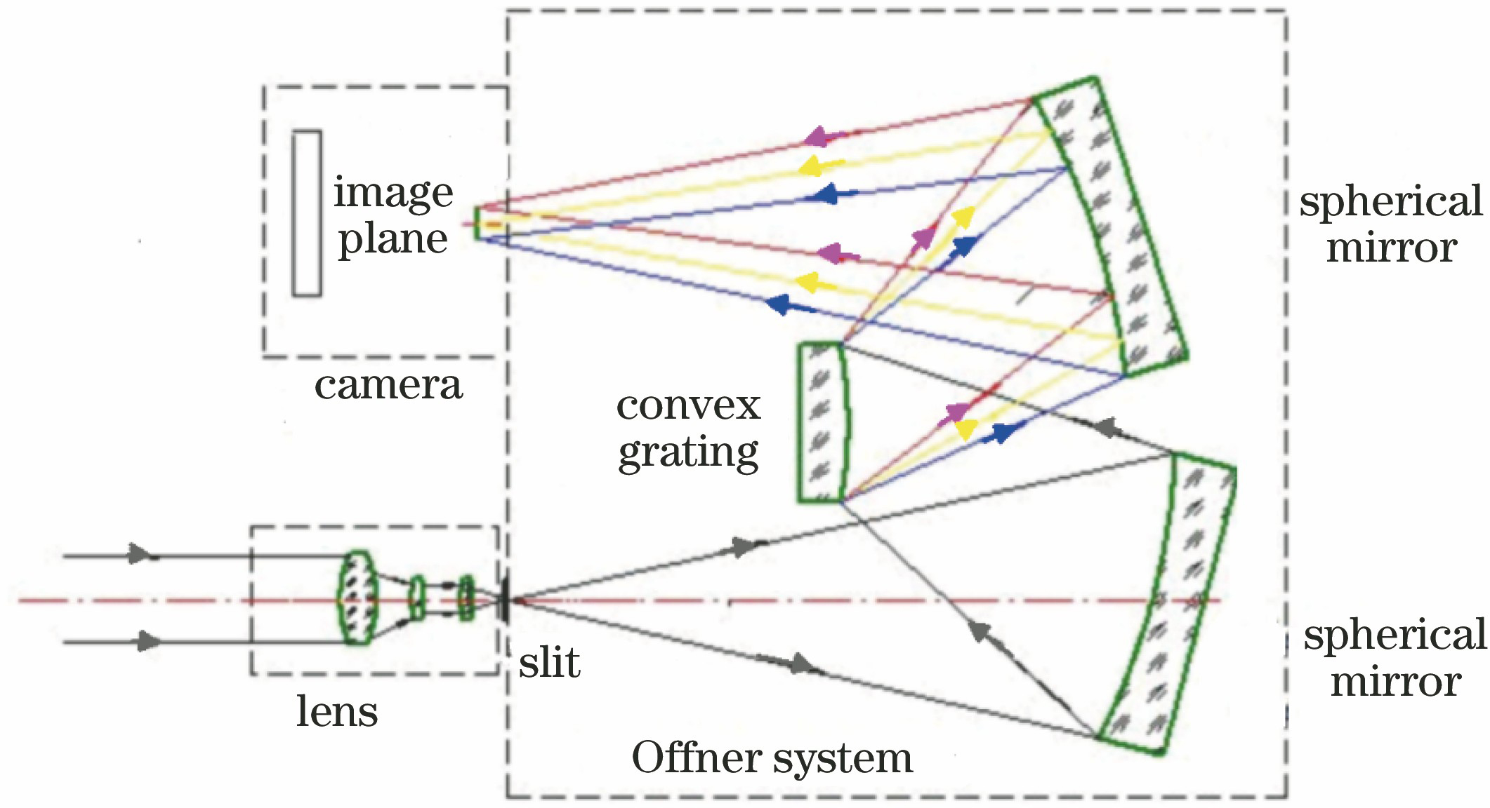
    Fig. 1. Diagram of Offner imaging spectrometer
    Schematic of blazed grating
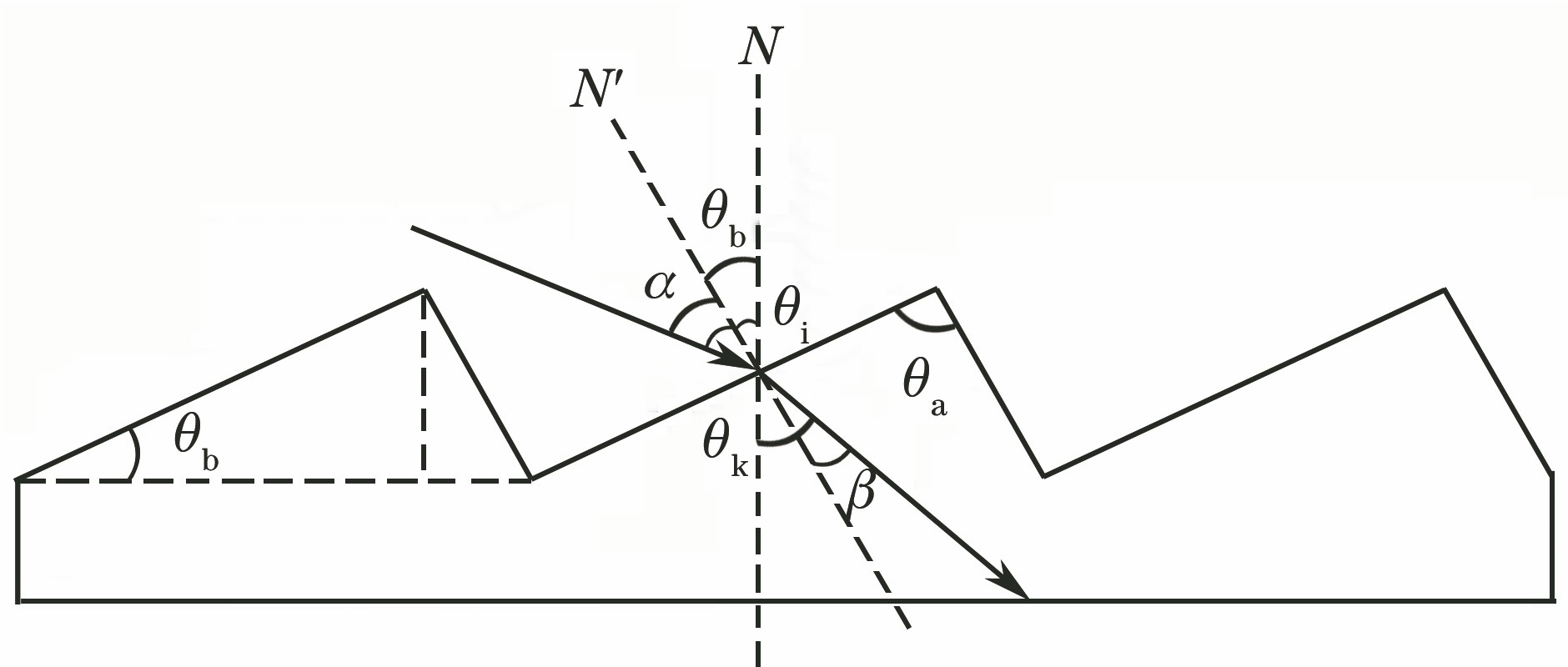
    Fig. 2. Schematic of blazed grating
    Structure of Lamina groove grating
    Fig. 3. Structure of Lamina groove grating
    Simulation curves of diffraction efficiency of rectangular groove convex grating. (a) Under different groove depths; (b) under different wavelengths
    Fig. 4. Simulation curves of diffraction efficiency of rectangular groove convex grating. (a) Under different groove depths; (b) under different wavelengths
    Simulation curves of diffraction efficiency of triangular groove convex grating. (a) Under different angles; (b) under different wavelengths
    Fig. 5. Simulation curves of diffraction efficiency of triangular groove convex grating. (a) Under different angles; (b) under different wavelengths
    Process diagram of convex grating
    Fig. 6. Process diagram of convex grating
    Deviation curves along Y-axis of machine under different conditions. (a) Under effect of wavefront; (b) under effect of ghost line; (c) standard deviation under effect of stray light
    Fig. 7. Deviation curves along Y-axis of machine under different conditions. (a) Under effect of wavefront; (b) under effect of ghost line; (c) standard deviation under effect of stray light
    Influence of residual fillet of diamond grave on diffraction efficiency of grating. (a) residual fillet diagram; (b) diffraction efficiency of grating with different residual fillet
    Fig. 8. Influence of residual fillet of diamond grave on diffraction efficiency of grating. (a) residual fillet diagram; (b) diffraction efficiency of grating with different residual fillet
    Real picture of developed convex grating
    Fig. 9. Real picture of developed convex grating
    Topography of zero-order optical wavefront of convex grating
    Fig. 10. Topography of zero-order optical wavefront of convex grating
    Profile of convex grating surface. (a) Surface profile of convex grating; (b) profile of convex grating
    Fig. 11. Profile of convex grating surface. (a) Surface profile of convex grating; (b) profile of convex grating
    Diagram of grating diffraction efficiency testing device
    Fig. 12. Diagram of grating diffraction efficiency testing device
    Diffraction efficiency curve of convex blazed grating
    Fig. 13. Diffraction efficiency curve of convex blazed grating
    Proposed system. (a) Structure of imaging spectrometer; (b) SWIR imaging spectrometer; (c) small airborne hyperspectral system
    Fig. 14. Proposed system. (a) Structure of imaging spectrometer; (b) SWIR imaging spectrometer; (c) small airborne hyperspectral system
    Hyperspectral data and SNR ratio curve obtained from flight experiment. (a) Hyperspectral image cube; (b) radiance spectral curve of typical ground objects; (c) SNR curve
    Fig. 15. Hyperspectral data and SNR ratio curve obtained from flight experiment. (a) Hyperspectral image cube; (b) radiance spectral curve of typical ground objects; (c) SNR curve
    ParameterContent
    Wavelength range1000-2500 nm
    Spectral resolution10 nm
    Focal length130 mm
    F numberF/2.2
    Linear dispersion7.5 nm/pixel
    Slit dimensionHeight:12 mm,width: 25 μm
    Detector array size320 pixel×256 pixel
    Detector pixel size30 μm×30 μm
    Table 1. Specifications of imaging spectrometer
    ParameterContent
    Wavelength range1000-2500 nm
    Curvature radius70 mm
    Diameter52 mm
    Groove density60 line/mm
    Diffraction order+1
    Incident angle30°
    Diffraction efficiency /%Above 60%
    Intensity ratio of stray lightBelow 0.1%
    Table 2. Parameters of convex grating
    StructureMaximumAverageAt initial wavelengthAt terminal wavelength
    Rectangular groove40.530732
    Triangular groove88.9653160.5
    Table 3. Diffraction efficiency of gratings with different groove types%
    No.d /μmNo.d /μmNo.d /μmNo.d /μm
    116.6981116.6642116.6523116.652
    216.6261216.7132216.6683216.646
    316.7081316.6192316.6243316.674
    416.6991416.7222416.6233416.616
    516.7051516.6852516.7143516.644
    616.6701616.7062616.6843616.696
    716.6541716.6292716.7003716.670
    816.6851816.6462816.6553816.678
    916.6961916.7292916.7233916.701
    1016.6392016.6953016.7014016.642
    Table 4. Data list of groove spacing
    Zhizhong Zheng, Zhong Yang, Liancun Xiu. Development and Application of Shortwave Infrared Convex Blazed Grating with High Diffraction Efficiency[J]. Acta Optica Sinica, 2020, 40(12): 1205002
    Download Citation