
Biwei Wu, Cong Wang, Zhi Luo, Junhui Li, Shu Man, Kaiwen Ding, Ji’an Duan. Controllable annulus micro-/nanostructures on copper fabricated by femtosecond laser with spatial doughnut distribution[J]. Chinese Optics Letters, 2020, 18(1): 013101
- Chinese Optics Letters
- Vol. 18, Issue 1, 013101 (2020)
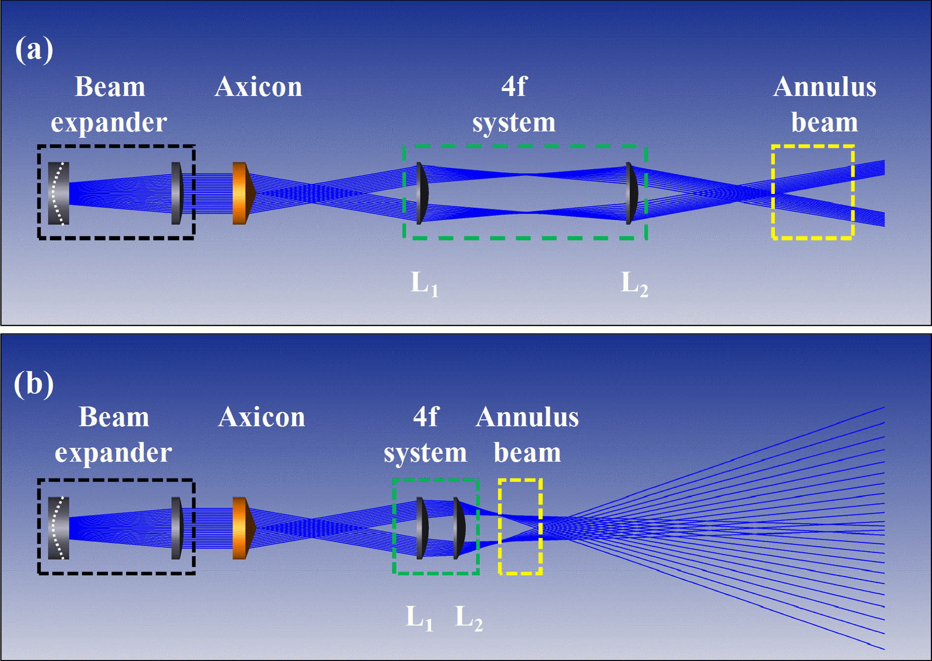
Fig. 1. Shaping optical path of the (a) traditional Bessel annular beam and (b) improved doughnut beam.
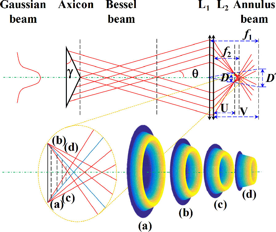
Fig. 2. Schematic diagram for the evolution of the improved doughnut beam.
Fig. 3. Experimental setup of doughnut shaping.
Fig. 4. Calculated annular beam with different diameters at different axial positions in the upper and middle panels, while the fabricated rings corresponding to the simulation positions are in the lower panels.
Fig. 5. Relationship between the movement and diameter of the fabricated rings. The red line is the simulated fitting line.
Fig. 6. SEM images of the rings fabricated by different linearly polarized fs laser improved doughnut beams. (I) The experimental results obtained without adding half-wave plates. The red arrows in the figure represent the initial polarization direction of the laser. (II) The experimental results obtained after adding half-wave plates. The blue dotted arrow represents the fast axis direction of half-wave plates, the red arrow is the initial polarization direction of laser as shown in (I), and the orange arrow is the polarization direction of the linearly polarized laser after passing through the half-wave plates.
|
Table 1. Measured and Calculated Diameters and Errors at Different Positions Corresponding to the Movement

Set citation alerts for the article
Please enter your email address
© Copyright 2018-2021 | Chinese Laser Press. All Rights Reserved 沪ICP备15018463号-20