• Photonics Research
  • Vol. 11, Issue 6, 968 (2023)
Cunzheng Fan1, Hao Li1、2, Keqing Zhang1, Huanhuan Liu3, Yixiang Sun1, Haoguang Liu1, Baoqiang Yan1, Zhijun Yan1、2, Deming Liu1, Perry Ping Shum3, and Qizhen Sun1、2、4、*
Author Affiliations
  • 1School of Optical and Electronic Information, Huazhong University of Science and Technology, Wuhan 430074, China
  • 2HUST-Wuxi Research Institute, Wuxi 214174, China
  • 3Guangdong Key Laboratory of Integrated Optoelectronics Intellisense, Department of Electrical and Electronic Engineering, Southern University of Science and Technology, Shenzhen 518055, China
  • 4Optics Valley Laboratory, Wuhan 430074, China
  • show less
    DOI: 10.1364/PRJ.485701 Cite this Article Set citation alerts
    Cunzheng Fan, Hao Li, Keqing Zhang, Huanhuan Liu, Yixiang Sun, Haoguang Liu, Baoqiang Yan, Zhijun Yan, Deming Liu, Perry Ping Shum, Qizhen Sun. 300 km ultralong fiber optic DAS system based on optimally designed bidirectional EDFA relays[J]. Photonics Research, 2023, 11(6): 968 Copy Citation Text show less
    (a) Schematic diagram of bidirectional EDFA relay module. (b) Schematic diagram of bidirectional EDFA relay-based DAS system.
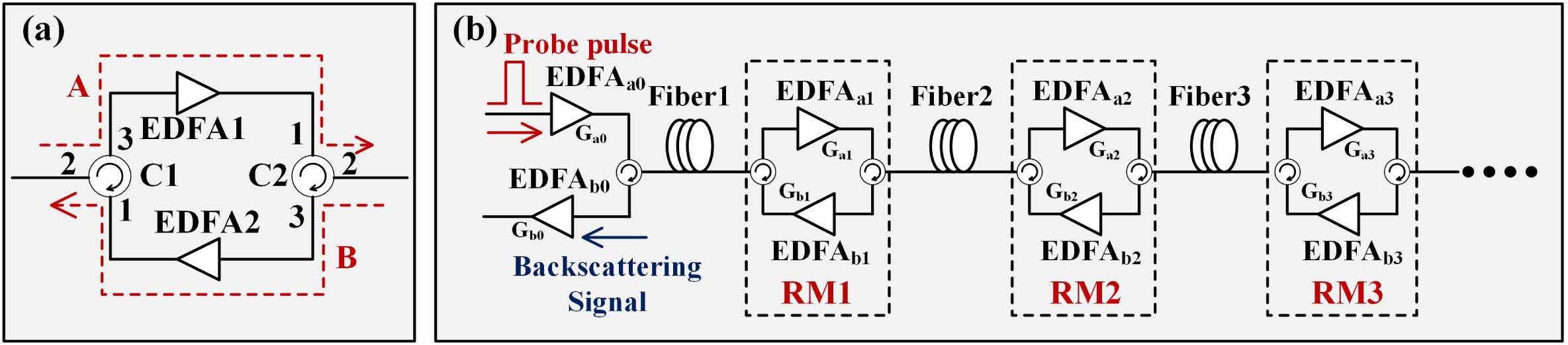
    Fig. 1. (a) Schematic diagram of bidirectional EDFA relay module. (b) Schematic diagram of bidirectional EDFA relay-based DAS system.
    Simulation results. (a) Signal and light leakage power in receiving end with different ER. (b) Power ratio of signal from span end and ASE noise of EDFA with different span length. (c) Maximum span length and maximum sensing distance with different span numbers.
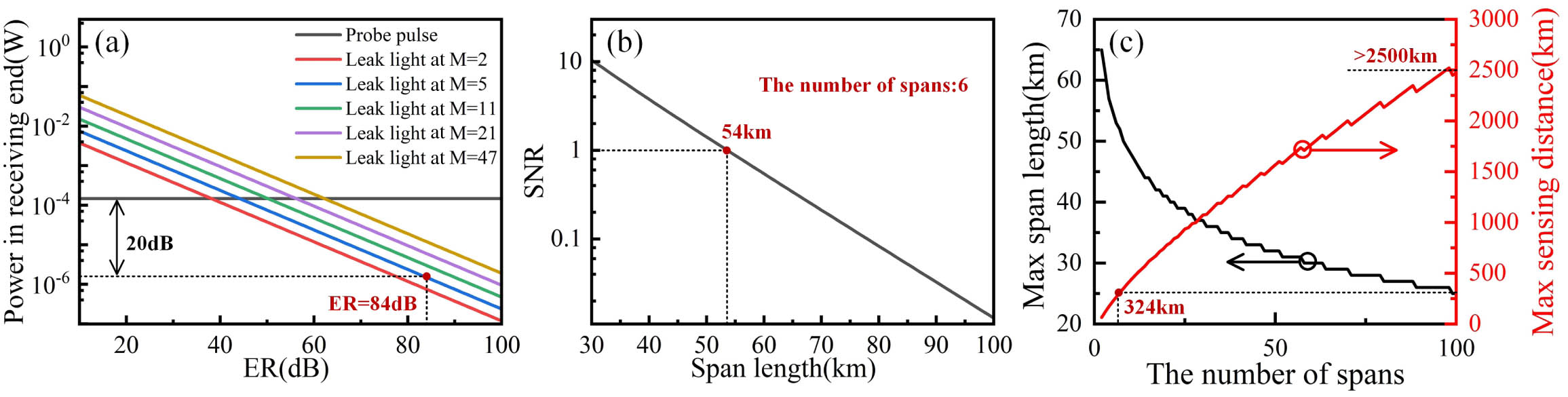
    Fig. 2. Simulation results. (a) Signal and light leakage power in receiving end with different ER. (b) Power ratio of signal from span end and ASE noise of EDFA with different span length. (c) Maximum span length and maximum sensing distance with different span numbers.
    Configuration of multispan relay amplification based DAS system.
    Fig. 3. Configuration of multispan relay amplification based DAS system.
    Temporal and spatial distribution patterns of the phase noise. (a) Cascaded AOMs DAS; (b) single AOM DAS. The probability distribution of the phase noise. (c) Cascaded AOMs DAS; (d) single AOM DAS. The RMS means root mean square.
    Fig. 4. Temporal and spatial distribution patterns of the phase noise. (a) Cascaded AOMs DAS; (b) single AOM DAS. The probability distribution of the phase noise. (c) Cascaded AOMs DAS; (d) single AOM DAS. The RMS means root mean square.
    Experiment results. (a) Backscattering signal of a probe pulse. Time domain signals at (b) 100.3 km, (c) 200.5 km, and (d) 300.2 km. (e) PSD signal at each span end.
    Fig. 5. Experiment results. (a) Backscattering signal of a probe pulse. Time domain signals at (b) 100.3 km, (c) 200.5 km, and (d) 300.2 km. (e) PSD signal at each span end.
    Signals at 300.2 km. (a) The amplitudes of sinusoidal signals with different drive voltages. (b) Frequency domain of sinusoidal signals with different frequencies.
    Fig. 6. Signals at 300.2 km. (a) The amplitudes of sinusoidal signals with different drive voltages. (b) Frequency domain of sinusoidal signals with different frequencies.
    Noise RMS possibility distribution at the first span end with span numbers from 1 to 6.
    Fig. 7. Noise RMS possibility distribution at the first span end with span numbers from 1 to 6.
    (a) ER measurement system. Optical spectra of (b) AOM1 and (c) AOM2 when AOMs are set as pulse mode and off mode.
    Fig. 8. (a) ER measurement system. Optical spectra of (b) AOM1 and (c) AOM2 when AOMs are set as pulse mode and off mode.
    SymbolsSignificance
    PthNonlinear power threshold of light
    MNumber of reply
    LmFiber length of m-th span
    EDFAa(b)mForward (backward) EDFA in m-th RM
    Ga(b)mGain of EDFAa(b)m
    Pa(b)mASE power excited by EDFAa(b)
    Pa(b)m,a(b)iASE power when Pa(b)m arrives at output end of EDFAa(b)i
    PpuslePower of probe pulse
    PleakLight leakage power of probe pulse
    ERPulse extinction ratio
    Table 1. Symbols of System Parameters in DAS Model
    ParametersOptimized Value
    M6
    ER>84  dB
    Lm (m=1,2,3)50  km
    Total sensing distance300  km
    Ga0Pth/Ppusle
    Gam (m=1,2,3)10 dB
    Gbm (m=0,1,2)10 dB
    Table 2. Optimized Parameters of Fiber Optic DAS
    Cunzheng Fan, Hao Li, Keqing Zhang, Huanhuan Liu, Yixiang Sun, Haoguang Liu, Baoqiang Yan, Zhijun Yan, Deming Liu, Perry Ping Shum, Qizhen Sun. 300 km ultralong fiber optic DAS system based on optimally designed bidirectional EDFA relays[J]. Photonics Research, 2023, 11(6): 968
    Download Citation