1School of Optical and Electronic Information, Huazhong University of Science and Technology, Wuhan 430074, China
2HUST-Wuxi Research Institute, Wuxi 214174, China
3Guangdong Key Laboratory of Integrated Optoelectronics Intellisense, Department of Electrical and Electronic Engineering, Southern University of Science and Technology, Shenzhen 518055, China
Optical fiber distributed acoustic sensing (DAS) based on phase-sensitive optical time domain reflectometry (φ-OTDR) is in great demand in many long-distance application fields, such as railway and pipeline safety monitoring. However, the DAS measurement distance is limited by the transmission loss of optical fiber and ultralow backscattering power. In this paper, a DAS system based on multispan relay amplification is proposed, where the bidirectional erbium-doped fiber amplifier (EDFA) is designed as a relay module to amplify both the probe light and the backscattering light. In the theoretical noise model, the parameters of our system are carefully analyzed and optimized for a longer sensing distance, including the extinction ratio (ER), span number, span length, and gain of erbium-doped fiber amplifiers. The numerical simulation shows that a bidirectional EDFA relay DAS system can detect signals over 2500 km, as long as the span number is set to be more than 100. To verify the effectiveness of the scheme, a six-span coherent-detection-based DAS system with an optimal design was established, where the cascaded acoustic-optic modulators (AOMs) were used for a high ER of 104 dB. The results demonstrate that the signal at the far end of 300.2 km can be detected and recovered, achieving a high signal-to-noise ratio of 59.6 dB and a high strain resolution of ε at 50 Hz with a 20 m spatial resolution. This is, to the best of our knowledge, a superior DAS sensing distance with such a high strain resolution.
1. INTRODUCTION
Distributed optical fiber sensing technologies based on fiber backscattering currently have attracted much attention. Researchers have proposed phase-sensitive optical time domain reflectometry (φ-OTDR) [1–4], Brillouin optical time domain reflectometry (BOTDR) [5], Raman optical time domain reflectometry (ROTDR) [6], and optical frequency domain reflectometry (OFDR) [7]. Due to the advantages of ultrahigh sensitivity, long-distance passive measurement, and undistorted acoustic detection, fiber optic distributed acoustic sensing (DAS) based on φ-OTDR has been applied in many areas, such as intrusion detection, pipeline, and railway safety monitoring [8–10].
In the applications mentioned above, the measurement distance is a key parameter, since the length of pipeline and railway usually reaches hundreds of kilometers. However, the measurement distance of DAS is limited by the transmission loss of optical fiber and ultralow backscattering power, which can only reach the level of 50 km without any amplification [11]. A long sensing distance will bring a large transmission loss, leading to a low Rayleigh backscattering power and a large phase noise. Therefore, a higher backscattering power is necessary for a longer sensing distance. A natural method to boost backscattering power is injecting the probe pulse with a higher peak power. However, it causes some undesirable nonlinear effect, such as modulation instability (MI) and stimulated Brillouin scattering (SBS) [12,13], which will consume power rapidly and bring noise significantly, which limits further the improvement of the detection distance.
To overcome the power limitation, researchers have proposed distributed amplification methods, in which the Raman pump light and Brillouin pump light are injected into the sensing fiber [14]. Because of the stimulated Raman scattering (SRS) effect and SBS effect, the pump light energy is transferred to the probe pulse during the forward transmission of the probe pulse. In 2014, Wang et al. first used distributed amplification methods in distributed vibration sensing (DVS) and reached 175 km [14,15]. In 2019, Chen et al. introduced DAS based on time-gated digital (TGD) OFDR combined with Raman inline amplification and achieved a 108 km sensing range [16]. However, rapid power consumption and the introduction of extra noise limit further improvement of the detection distance.
Sign up for Photonics Research TOC. Get the latest issue of Photonics Research delivered right to you!Sign up now
Another method to extend the sensing distance is multispan relay amplification, including erbium-doped fiber amplifier (EDFA) relay amplification [17] and distributed Raman relay amplification [18]. Because Raman amplification needs complex and expensive devices, EDFA is most commonly used as a relay amplifier for a long sensing distance. The Er-doped fibers are used to amplify the bidirectional light signal and the sensing length can reach up to 100 km [17]. However, because the power of the forward probe pulse is much larger than that of the backscattering light, most of carriers are consumed by the forward probe light, and the backscattering light is not magnified effectively, which limits the span distance. Besides, because the EDFA stimulates the amplified spontaneous emission (ASE) noise and degrades the extinction ratio (ER) of the probe pulse, both the length and number of spans are limited, which hinders the further improvement of the sensing length [11].
In this work, a DAS system based on multispan relay amplification is proposed, where a bidirectional EDFA module was designed as the relay module (RM) to amplify both the probe light and backscattering light [11]. First, a noise model of the fiber DAS was established, where the parameters of our system were carefully analyzed and optimized for a longer sensing distance, including the ER, span number, span length, and EDFA gain. The simulation result shows that a bidirectional EDFA relay DAS system can detect signals over 2500 km as long as the span number is set to more than 100. Furthermore, a coherent-detection-based DAS system with an optimal design was established to verify the effectiveness of the scheme with six spans, where the cascaded acoustic-optic modulators (AOMs) were used for a high ER of 104 dB. The results show that the signal at 300 km can be detected, achieving a high signal-to-noise ratio (SNR) of 59.6 dB and a high strain resolution of ε at 50 Hz with a 20 m spatial resolution, which is, to the best of our knowledge, a superior DAS sensing distance with such a high strain resolution level.
2. THEORETICAL MODEL AND OPTIMAL DESIGN OF BIDIRECTIONAL EDFA RELAY-BASED FIBER OPTIC DAS SYSTEM
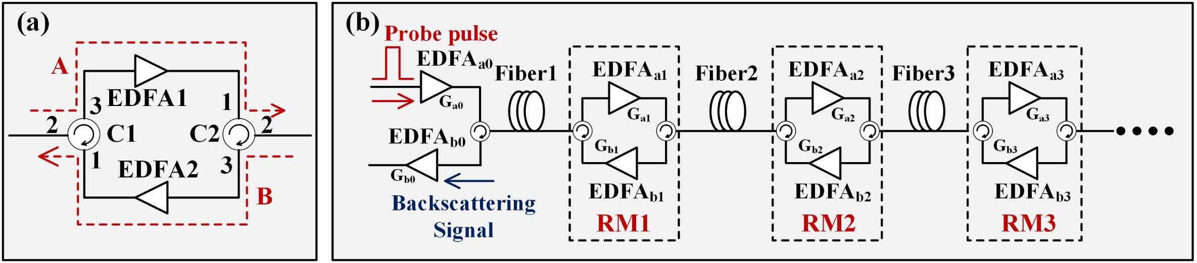
Figure 1.(a) Schematic diagram of bidirectional EDFA relay module. (b) Schematic diagram of bidirectional EDFA relay-based DAS system.
A. Power Limitation of Bidirectional EDFA Relay DAS
A higher probe light power can bring a higher SNR and lower noise to DAS. However, the high probe light power will excite some undesired nonlinear effects, such as stimulated Brillouin scattering (SBS) and modulation instability (MI).
The MI nonlinear effect originates from the interaction of the dispersion and self-phase modulation, which will excite the amplified spontaneous emission (ASE) noise in MI gain bandwidth [19]. As a result, the MI gain will bring a serious power depletion and a fluctuation of the probe light, and then deteriorate the SNR of DAS. Therefore, limiting the probe pulse power and avoiding the MI nonlinear effect are essential for a better SNR. Previous studies have shown that the MI nonlinear effect has a greater influence and stricter restriction on DAS with a power threshold of 400 mW [19,20], which is considered in our model. However, the MI nonlinear effect will increase with distance, and then a longer sensing distance system will suffer a tighter power restriction. Fortunately, the MI nonlinear effect can be effectively suppressed through dispersion compensation at each span. Since the MI nonlinear effect originates from the interaction of the dispersion and self-phase modulation, if the dispersion is compensated, the gaining modulation is mainly a phase modulation, while the amplitude noise is not significantly affected and may, in some cases, even decrease [21].
B. Dispersion
A narrow linewidth laser, with a linewidth of is normally used as the light source in a DAS system, which corresponds to a spectral width at the 1550 nm center wavelength. Considering the SMF dispersion and the 1000 km level sensing length, the probe pulse will have an expansion of with a 2000 km (1000 km2) propagation distance, which is much less than the ns-level pulse width. Therefore, the dispersion can be ignored in the ultralong-distance DAS.
C. Optical Noise Analysis
In a bidirectional EDFA relay-based fiber optic DAS system, the optical noise mainly comes from two sources: ASE noise from the EDFAs and modulator light leakage noise [11]. Since the ASE noise of an EDFA is determined by EDFA gain and is hardly affected by the input power, the power of ASE noise does not change with time in a certain system with constant EDFA gain. What is more, due to a very small duty ratio, the modulator light leakage in DAS can be considered as a CW, and thus the leakage noise is also time-invariant with a certain system.
Therefore, although the backscattering signals from different distances have different propagation paths and arrival times, they will carry optical noise with the same power. To ensure the same SNR in each span end, the powers at each span end must be consistent; thus, the two EDFAs of the m-th RM must exactly compensate the bidirectional transmission loss of the ()-th span, which can be expressed as where and are the gains of forward and backward EDFA in the -th RM, respectively, represents the length of the ()-th span, and is the Rayleigh scattering coefficient, which represents the power ratio of the Rayleigh scattering light to the incident light per unit length.
1. ASE Noise of EDFA
The ASE noise of EDFA is determined by its gain , which can be expressed as [22] where is the ASE noise power, G is the gain of EDFA, is Planck constant, is the optical frequency, is the optical bandwidth, and is the spontaneous emission coefficient as , where and are, respectively, the numbers of the ground state particle and the excited state particle. Ideally, the particle number is completely reversed and . In a bidirectional EDFA relay DAS system, the ASE noise of all EDFAs will be finally superimposed at the photodetector of receiving end, where the forward EDFA ASE is via Rayleigh backscattering and relay amplification while the backward EDFA ASE is via relay amplification directly.
Then, the contributions of forward and backward EDFAs to the ASE noise in the receiving end are compared, where the ASE power ratio between forward and backward EDFAs in the m-th RM is (see Appendix A) where is the number of RM (corresponding to spans), is the capture factor, is the EDFA gain, and is the span length. Generally, is less than 6. For single-mode fiber, and . We set the span length to be 50 km as an example, and then will be 10 and the ratio will be less than 0.059. Since the two ASE lights have the same path from the output end of to the receiving end, the ASE noise of the forward EDFA is much less than that of the backward EDFA in the receiving end and it can be ignored.
Therefore, the gain of the forward EDFA should be set as large as possible for less total ASE noise. Considering the power limitation of the MI nonlinear effect, each forward EDFA can amplify the probe pulse to the MI nonlinear threshold as where is nonlinear power threshold of light, is the power of the probe pulse, and and are the gain of and , respectively, as shown in Fig. 1(b). In other words, the gain of the forward EDFA in the m-th relay must exactly compensate the loss of the -th span fiber. Moreover, to ensure the optical power at each span end is consistent, the backward gain should be set as
Note that the same gains of forward and backward EDFAs are the optimal parameter settings, which are not artificially set. Therefore, the total ASE power in the receiving end can be expressed as (see Appendix A) where is the ASE light power excited by , and the ASE noise of the forward EDFA has been ignored. Equation (6) indicates that the ASE noise of the bidirectional EDFA relay DAS system is equal to the sum of the backward EDFAs’ ASE noise and will be increased with an increase in the relay number.
2. Light Leakage Noise of Modulator
A modulator is usually used to modulate the CW laser into the probe pulse in a DAS system. Because the modulator is not ideal, a small amount of light will pass the modulator even when the modulator is turned off, which is called leak light. The leak light will be scattered back to the receiving end from the whole sensing fiber and interfere with the signal, which will be demodulated as noise. Since a longer sensing fiber brings a larger power backscattering leak light, the light leakage noise must be considered in our long-distance DAS scheme.
The pulse is usually used to characterize the leak light performance of the modulator, where is the power of the leak light. If the signal power is much larger than the light leakage power, the light leakage noise can be ignored. Therefore, the power should be satisfied as where is the scattering power of the probe pulse from the span end and is the leak light power in the receiving end. The condition requires that the pulse ER should be large enough to meet (see Appendix B) where is the pulse width and is speed of light in fiber.
D. Simulation of the Optimally Designed System
To further study the light leakage noise, a simulation was conducted, where the pulse width was set as 200 ns and the span length was set as 50 km. According to the theoretical analysis in Section 2.C.2 and Appendix B, the leak light power and the scattering power of the probe pulse from the span end were compared under different RM numbers and ER. As shown in Fig. 2(a), a long sensing length brings a large light leakage noise power and a large ER brings a low noise power. For a 5-RM (corresponding to six spans and 300 km) sensing system, the ER must be larger than 84 dB to make sure the light leakage noise can be ignored, where is 20 dB larger than . Because existing pulse modulation devices such as AOMs, electro-optic modulators (EOMs), and semiconductor optical amplifiers (SOAs) cannot reach such a high ER, a cascaded pulse modulation was applied to our method so the double pulse modulation would cause a higher ER.
Figure 2.Simulation results. (a) Signal and light leakage power in receiving end with different ER. (b) Power ratio of signal from span end and ASE noise of EDFA with different span length. (c) Maximum span length and maximum sensing distance with different span numbers.
Next, the farthest measurable distance of the proposed bidirectional EDFA relay DAS system is discussed. Assuming that the ER is large enough to ignore light leakage noise, only the SNR of signal from span end and ASE noise of EDFA was considered. Therefore, the theoretical analysis in Section 2.C.1 and Appendix A was used for the following simulation. First, the number of spans was fixed and the span length was changed to calculate the SNR. The conditions of six spans are shown in Fig. 2(b) as an example, and the SNR will be decreased with an increase in the span length, where the signal will be submerged in noise if the SNR is less than 1. Therefore, the span length at is the maximum span length recorded and presented as the black line in Fig. 2(c). In addition, the total sensing distances were calculated and presented as the red line in Fig. 2(c). Note that the maximum sensing distance will be boosted with an increase in the span number although the maximum span length is decreased, which can even reach 2500 km with 100 spans. In fact, for a 2500 km system, an 88 dB ER was needed to make sure the light leakage noise could be ignored, according to Eqs. (7) and (8). Compared to the condition of the 300 km system, although the leak light noise of 2500 km had a significant increase, the probe power in span end was also improved because of the shorter span length. Therefore, the ER did not significantly increase, and the cascaded pulse modulation could meet the demand.
Considering the device limitations, a six-span DAS system with 5 RMs was built to verify our scheme, and the corresponding optimally designed parameters are shown in Table 2, including more than 84 dB ER, span length, 300 km total sensing distance, and 10 dB EDFA gains.
Optimized Parameters of Fiber Optic DAS
Parameters
Optimized Value
M
6
ER
()
Total sensing distance
()
10 dB
()
10 dB
3. EXPERIMENTAL SETUP AND RESULT
To verify the bidirectional EDFA relay DAS method, a prototype system with five RMs was built. The configuration is shown in Fig. 3, where the coherent detection is employed [23] and the parameters are referred to in Table 2. The CW light from the narrow linewidth laser (NLL; X15 erbium lasers, NKT Photonics) is split into the probe light and local light by a optical coupler (OC1, with a splitting ratio of 1:9). The probe light is injected into the cascaded AOMs (AOM1: 80 MHz frequency shift; AOM2: 200 MHz frequency shift, G&H) to generate optical pulses with a high ER. After being amplified by EDFA1 (BG-pulse-EDFA, Beogold Technology), the probe pulses are transmitted into the sensing fibers. At the receiver end, the backscattering light of the probe pulses is mixed with the local light in OC2 (with a splitting ratio of 1:1) and generates the beat signal. After that, the outputs are converted into electrical signal by balanced photodetectors (BPDs; MBD-350M-A, Guangshi Technology), which is sampled by a data acquisition card (PXI-5154, 1 GHz, NI) and finally demodulated. To reduce the bandwidth requirement of the acquisition card, the local light is injected into AOM3 (G&H) with 200 MHz frequency shift. Therefore, the beat frequency is decreased from 280 to 80 MHz, bringing a more complete wave acquisition. What is more, the AOM3 can bring the signal frequency to a flat response range of BPD for a larger responsivity and less noise, since the BPD in the system has a bandwidth of 350 MHz. In addition, six optical fiber under test (FUT) segments were used as the sensing fibers, with lengths of 50.2 km, 50.1 km, 50.3 km, 49.9 km, 49.7 km, and 50.0 km, respectively. In addition, five RMs are connected between two adjacent FUTs for bidirectional optical amplification. The far-end of each FUT is wrapped around piezoelectric transducers (PZTs) which are used to simulate the acoustic signals, corresponding to the sensing distances of 50.2 km, 100.3 km, 150.6 km, 200.5 km, 250.2 km, and 300.2 km, respectively. Since the ERs of AOM1 and AOM2 are 44.39 dB and 59.60 dB, respectively, the ER of the cascaded AOMs can reach 104 dB. See the Appendix C for specific measurement and analysis. Therefore, unlike the single AOM DAS, the light leakage noise of the cascaded AOM DAS can be ignored completely with a 300 km sensing distance.
Figure 3.Configuration of multispan relay amplification based DAS system.
First, the signals of the single AOM DAS and the cascaded AOMs DAS were compared. The probe pulse with a 200 ns width and 300 Hz repetition frequency was modulated by AOM1 and cascaded AOMs (AOM1+AOM2), respectively, which was injected into a 50 km sensing fiber. The acoustic sensing results are shown in Fig. 4, where the temporal and spatial distribution patterns of the phase noise are plotted in Figs. 4(a) and 4(b), and the probability distribution of the phase noise is plotted in Figs. 4(c) and 4(d). Note that the possibilities of root mean square (RMS) were 94.4% and 2.5% for a cascaded AOMs DAS system and a single AOM DAS system, respectively, which demonstrates that the cascaded AOMs DAS has a much lower noise level because of the higher ER.
Figure 4.Temporal and spatial distribution patterns of the phase noise. (a) Cascaded AOMs DAS; (b) single AOM DAS. The probability distribution of the phase noise. (c) Cascaded AOMs DAS; (d) single AOM DAS. The RMS means root mean square.
Further, the DAS system with five RMs and six spans was verified. In the experiment, the probe pulse with a 200 ns pulse width and 300 Hz pulse repetition frequency was injected into the FUT. Due to the limitation of the distance bandwidth product [24], the longest detection distance was 333 km, which is suitable for the system shown in Fig. 3. By setting the EDFAs as proper values, the RMs can effectively amplify the signal, and the beat frequency signal can be detected clearly even in the span ends, as shown in Fig. 5(a). Further, the six PZTs in each span end are driven by a sinusoidal wave with an amplitude of 1 V and a frequency of 50 Hz to simulate acoustic signals. The sinusoidal waves at 100.3 km, 200.5 km, and 300.2 km are, respectively, plotted in Figs. 5(b)–5(d). Note that the sinusoidal waves at different locations can be recovered with high fidelity. In addition, the power spectral density (PSD) of the six PZTs was calculated and is shown in Fig. 5(e), which illustrates that the signals in different span ends have the same noise level of and an SNR of 59.6 dB. These results can verify that the bidirectional EDFA relay DAS method is effective and the sensing distance can reach up to 300 km with six spans.
Figure 5.Experiment results. (a) Backscattering signal of a probe pulse. Time domain signals at (b) 100.3 km, (c) 200.5 km, and (d) 300.2 km. (e) PSD signal at each span end.
Moreover, we applied different amplitude signals into the fiber through changing PZT6’s drive voltage from 0.5 to 4 V. The corresponding amplitudes are shown in Fig. 6(a), where the 10 group signals are recorded to gain the error bar. Note that the bidirectional EDFA relay DAS has a great linear strain response with at 300.2 km. Because the voltage-strain conversion relationship of PZT is 0.092 με/V, the strain sensitivity can be calculated as με. According to the strain sensitivity, noise level, and spatial resolution, the strain resolution could be calculated as ε at 50 Hz with a 20 m spatial resolution. Then, the different frequency signals were applied on PZT6 and the frequency response was plotted in Fig. 6(b), which shows that all frequencies can be effectively detected.
Figure 6.Signals at 300.2 km. (a) The amplitudes of sinusoidal signals with different drive voltages. (b) Frequency domain of sinusoidal signals with different frequencies.
Finally, to explore the influence of the span number on the signal quality, we gradually increased the spans from one to six and monitored the phase noise at the end of the first span. Specifically, the 60 s signals from 962 channels were divided into six groups to calculate the noise RMS. After that, the noise RMS distribution was counted through the total 5772 sets (962 channels 6 groups per channel) of RMS data. As shown in Fig. 7, the noise obviously increases when the number of spans increases, and the possibilities of are 7.54%, 17.67%, 22.35%, 24.27%, 31.62%, and 44.35%, respectively when the system has 1–6 spans. Note that we added the span numbers and recorded noise signals at the same location, as shown in Fig. 7. The results are consistent with the conclusions in the model: more spans will bring a large amount of noise and limit further improvement of the detection range; however, the noise level of each span end will be consistent if the number of spans remains unchanged, which has been proven in the theoretical model and shown in Fig. 5.
Figure 7.Noise RMS possibility distribution at the first span end with span numbers from 1 to 6.
Note that the sensing distance can reach more than 2500 km by increasing the span numbers, although it results in a larger amount of noise and a shorter span length. However, the NLL in our experiment has a 200 Hz linewidth, corresponding to a 1500 km coherence length and a 750 km sensing distance. The coherent detection DAS scheme, which detects the interference signal between the backscattering light of the probe pulses and the local light, cannot work in the 2500 km system. Therefore, the DAS based on the phase-generated carrier algorithm or 33 coupler structure may be used for 2500 km sensing. In addition, the distributed Raman amplification can be integrated in the future, achieving a longer sensing distance with a smaller number of spans.
4. CONCLUSION
In summary, we have proposed and demonstrated a DAS system based on multispan relay amplification. First, a bidirectional EDFA RM was designed that can amplify both the forward and backward optical signal. Then the noise model of the proposed scheme was established, where the parameters of our system were carefully analyzed and optimized for a longer sensing distance, including ER, span number, span length, and EDFA gain. Furthermore, a six-span prototype system was built, which can recover signals at 300.2 km with a high SNR of 59.6 dB and a high strain resolution of ε at 50 Hz with a 20 m spatial resolution. The scheme greatly expands the application scope of fiber optic DAS, especially in fields requiring long distances measurement such as railway monitoring and tunnel safety.
APPENDIX A: ASE NOISE ANALYTICAL MODEL OF EDFA
The ASE noise of EDFA is determined by its gain , which can be expressed as [19] where is the ASE noise power, is the EDFA gain, is the Planck constant, is the optical frequency, is the optical bandwidth, and is the spontaneous emission coefficient as where and are the numbers of the ground state particle and excited state particle, respectively. Ideally, the particle number is completely reversed and . In bidirectional EDFA relay DAS, the ASE noise of all EDFAs will be finally superimposed at the photodetector of the receiving end, where the forward EDFA ASE is via Rayleigh backscattering and relay amplification while the backward EDFA ASE is via relay amplification directly.
Then, the contributions of forward and backward EDFAs to ASE noise in the receiving end are compared, where the forward and backward EDFAs in the m-th RM ( and ) are analyzed. For the , the ASE light will be scattered by the farther span as where is the number of RM (corresponding to spans), is the ASE power excited by , is the power when arrives at the output end of , and are the gain of and , is the fiber length of the -th span, and is capture factor (the ratio of backscattered light to all scattered light). In Eq. (A3), the summation sign shows the superposition of Rayleigh scattering from the ()-th span to the ()-th span, and the multiplication term represents the transmission loss and EDFA gains introduced from the calculation of the -th span Rayleigh scattering. To facilitate analysis, we assume each span has the same length . Considering the power consistent constraint, the multiplication terms are equal to 1. Therefore, Eq. (A3) can be simplified as
Then, the ASE light power excited by is
When the two EDFAs have the same gain , the ASE power ratio is
Generally, is less than 6. For the single-mode fiber, and . When we set the span length as 50 km as an example, then the will be 10 and the ratio will be less than 0.059. Since the two ASE lights have the same path from output end of as the receiving end, the ASE noise of forward EDFA is much less than that of the backward EDFA in the receiving end and it can be ignored.
Therefore, the gain of the forward EDFA should be set as large as possible for a less total ASE noise. Considering the power limitation of MI nonlinear effect, each forward EDFA can amplify the probe pulse to the MI nonlinear threshold as where and are the gain of and , respectively, as shown in Fig. 1(b). Moreover, to ensure a power consistent constraint, the backward gain should be set as
Therefore, the total ASE power in receiving end can be expressed as where is equal to 1 and . Equation (A9) indicates that the ASE noise of bidirectional EDFA relay DAS is equal to the sum of the backward EDFA ASE noise and will be increased as the number of relays increases.
APPENDIX B: LIGHT LEAKAGE NOISE ANALYTICAL MODEL OF MODULATOR
In a DAS system, the modulator is usually used to modulate the CW laser into the probe pulse. Because the modulator is not ideal, a small amount of light will pass the modulator even when the modulator is turned off, which is called leak light. The leak light will be scattered back to the receiving end from the whole sensing fiber and interfere with the signal, which will be demodulated as a noise. Since a longer sensing fiber brings a larger power backscattering leak light, the light leakage noise must be considered in our long-distance DAS scheme.
Usually, the pulse is used to characterize the leak light performance of the modulator, where is the power of the leak light. Since the probe pulse has a very small duty ratio in DAS, the leak light can be considered as a CW. For our bidirectional EDFA relay DAS, the power of the leak light in receiving end can be expressed by the superposition of Rayleigh scattering from the whole fiber as where the EDFA gains are set as the optimal parameters in Eqs. (A7) and (A8). The indicates the Rayleigh scattering from a span fiber and indicates the span number. What is more, the scattering power of the probe pulse from the span end can be expressed as where is the pulse width and is speed of light in the fiber. Since the signal from each span end has the lowest power, the light leakage noise can be ignored only when
Therefore, the pulse ER must be large enough to meet
APPENDIX C: ER MEASUREMENT OF CASCADED AOMs
In the paper, the ERs of the two AOMs were measured separately. As Fig. 8(a) shows, the CW light from the narrow linewidth laser (NLL) was injected into the cascaded AOMs and finally detected by an optical spectrum analyzer (OSA; AQ6374, Yokogawa). First, we turned on the AOM2, and recorded the light power when AOM1 was, respectively, set as off-mode and pulse modulation mode. Similarly, we then turned on AOM1, and recorded the light power when AOM2 was, respectively, set as off-mode and pulse modulation mode. As shown in Table 3, the optical spectrum under the four conditions was measured, and their spectral peak powers were recorded, where “Pulse” means the AOM was used for pulse modulation with a 200 ns pulse width and 1 ms pulse repetition period .
Figure 8.(a) ER measurement system. Optical spectra of (b) AOM1 and (c) AOM2 when AOMs are set as pulse mode and off mode.
Therefore, the ER can be calculated as where and are the ERs of AOM1 and AOM2, respectively. The optical spectra are shown in Fig. 8. According to Eq. (C1), the ER of the cascaded AOM can reach 104 dB while the ERs of AOM1 and AOM2 are only 44.39 dB and 59.6 dB, respectively. In the 300 km system, the ER must be larger than 84 dB to make sure the light leakage noise can be ignored. Therefore, unlike the single AOM DAS, the light leakage noise of the cascaded AOM DAS can be completely ignored.
[6] H. Wu, C. Zhao, R. Liao, Y. Chang, M. Tang. Performance enhancement of ROTDR using deep convolutional neural networks. 26th International Conference on Optical Fiber Sensors, TuE16(2018).
[7] Y. Lv, H. Li, Z. Yang, Z. Yan, J. Zang, Q. Sun. Highly accurate 3D shape sensing based on special fiber OFDR system assisted with ICP algorithm. 27th International Conference on Optical Fiber Sensors, Tu1.7(2022).
[11] C. Fan, H. Li, B. Yan, Z. Yan, Q. Sun. 246 km long distance fiber optic DAS system based on multi-span bidirectional EDFAs and cascaded AOMs. Optical Fiber Communication Conference, W4D.4(2022).
[13] C. Fan, H. Li, B. Yan, Y. Sun, H. Liu, K. Ai, Z. Yan, Q. Sun. Modulation instability suppression for fiber optic DAS assisted with dual wavelength lasers. Conference on Lasers and Electro-Optics, JW3B.92(2022).
[18] E. Ip, Y.-K. Huang, M.-F. Huang, F. Yaman, G. Wellbrock, T. Xia, T. Wang, K. Asahi, Y. Aono. DAS over 1,007-km hybrid link with 10-Tb/s DP-16QAM co-propagation using frequency-diverse chirped pulses. 2022 Optical Fiber Communications Conference and Exhibition (OFC), 1-3(2022).