Guanchao Wang, Li Li, Chenxiang Liu, Shuai Li, Wenpeng Guo, Yueying Jia, Zhenghao Li, Hao Tian, "Tunable terahertz slow light with hybrid coupling of a magnetic toroidal and electric dipole metasurface," Photonics Res. 11, 494 (2023)
Copy Citation Text
We present a hybrid coupling scheme of a magnetic toroidal and electric dipole metasurface with suppressed radiation loss, which can produce the tunable plasmon-induced transparency (PIT) with an enhanced slow-light effect in the terahertz regime. The terahertz metasurface is constructed by nesting a dual-split ring resonator (DSRR) inside a ring resonator (RR) to exploit the destructive coherence of hybrid electromagnetic mode coupling at the PIT resonance. The polarization-dependence excitation performs the active tunability of a PIT-induced group slowing down by rotating the polarization angle, experimentally achieving a maximum group delay of 3.5 ps. Furthermore, the modified terahertz metasurface with a four-split ring resonator (FSRR) nested in an RR is prepared on photoconductive silicon, demonstrating the pump-controllable group delay effect at the PIT resonance. The large group delay from 2.2 to 0.9 ps is dynamically tunable by adjusting the pump power. The experimental results are in good accord with the theoretical simulations.
1. INTRODUCTION
Terahertz electromagnetically induced transparency (EIT) is greatly of interest in control of terahertz waves with the slowing down of group velocity, enhancement of phase dispersion, and nonlinearity between field–matter interaction [1–4]. It brings about quite promising applications in terahertz switching, terahertz pulse delay, and terahertz communication [5–8]. Particularly, EIT has the superior capability of slowing down the speed of the terahertz wave along with lossless transmission of the terahertz signal, which is the terahertz slow-light effect. Previously, the EIT phenomenon was observed in light–atomic interaction systems, but it requires harsh experimental conditions involving stable pumping and ultralow temperature [3,9,10]. Recently, the emergence of electromagnetic metamaterials has produced such an EIT-like phenomenon, called plasmon-induced transparency (PIT) [11–13]. PIT can perform under common conditions, avoiding requirements of quantum optical implementation in multi-level atomic systems [14–17]. Such PIT in metamaterial regime is basically not limited to quantum mechanical systems [18–22]. By exploiting the strong mode-coupling schemes of split ring resonators, ring resonators (RRs), cut wires, and fishnets [18,19,23], artificial meta-atoms can geometrically modify the electromagnetic coherence characteristics in the terahertz regime for the realization of PIT [24–26]. Interestingly, the PIT effect occurring in the resonant absorption spectra features a high- transparent window, at which the unusual phase dispersion can be aroused to induce large group delay [15,16]. Moreover, the tunability of PIT-induced slow light can perform with the introduction of semiconductors, graphene, liquid crystal, and phase transition materials [27–30]. Note that, previously, terahertz PIT metamaterials operated mostly via the dipole–dipole coupling between the fundamental modes with notable radiation damping loss [31–34]. This basically suppresses the abnormal phase dispersion at the PIT window, so it limits the achievable group delay of slow light to about 1 ps, especially small in the terahertz regime [11,35–37].
In the paper, we present a unique scheme of radiation loss-suppressed terahertz PIT by exploiting the hybrid coupling of a magnetic toroidal and electrical dipole metasurface. The metasurface is constructed by nesting a dual-split ring resonator (DSRR) inside an RR. Due to the polarization-dependent excitation, the active tunability of PIT-induced group delay is performed by rotating the polarization angle, experimentally achieving a maximum group delay of 3.5 ps. Furthermore, the modified terahertz metasurface with a four-split ring resonator (FSRR) nested in an RR is prepared on the photoconductive silicon, experimentally demonstrating the pump-controllable group delay at the PIT resonance. A large group delay of 2.2–0.9 ps can be dynamically tuned in the pump power range of up to 800 mW. The underlying mechanisms of both polarization- and pump-controllable PIT-induced slow light are discussed with the help of the coupled oscillator model and numerical simulation showing good accordance with the experiment.
2. RESULTS AND DISCUSSION
A. Polarization-Controlled PIT in the DSRR/RR Metasurface
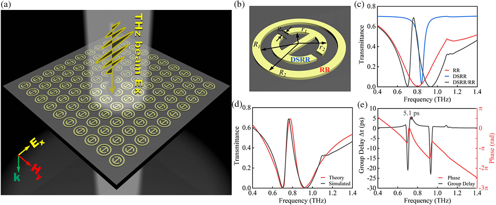
Generally, the factors of PIT resonance by the coupling of fundamental dipole modes are low in the terahertz regime due to the notable radiative damping loss [24,37]. It is hard to arouse strong abnormal phase dispersion at low- PIT resonance. Here, the hybrid coupling scheme of a magnetic toroidal and electric dipole metasurface with suppressed radiation loss is exploited to improve high- PIT resonance at the low-damping destructive coherence. The metasurface consists of the periodical pattern of a unit cell while nesting a DSRR inside an RR, as shown in Figs. 1(a) and 1(b). Under the condition of the parameters presented in Fig. 1(b), DSRR and RR exhibit very close eigen frequencies in Fig. 1(c), but each induces different modes. The variation of the polarization angle affected the mode response of the DSRR, but not for the RR with rotation invariance. The PIT effect generated by DSRR and RR coupling is closely related to the polarization angle. In Fig. 1(c), a sharp transparent window in the broad transmission dip is contributed to by the destructive interference between the two different modes. The DSRR can excite the surface loop current to produce a pair of opposite magnetic dipoles, forming a magnetic toroidal mode with the closed magnetic field lines [26,38,39]. The feature of the magnetic toroidal mode can basically support the high- sharp resonance due to the radiation loss suppressed. Taking into account the noncentric symmetry of the DSRR, the excitation of the magnetic toroidal mode is strongly dependent on the incident polarization angle and substrate dielectric permittivity [40,41]. Meanwhile, the RR can excite the electric dipole mode independent of incident polarization [11,42]. In the hybrid DSRR/RR structure, the magnetic toroidal mode can make strong coupling with the electric dipole mode produce the low loss destructive interference at the resonance as shown in Figs. 1(c) and 1(d). In the physical mechanism of PIT, the resonant absorption on both sides of the peak corresponds to the resonance of RR. This unusual PIT window is attributed to the generation of destructive coherence in the coupling process of different modes of RR and DSRR. At PIT resonance, the distinct abnormal phase dispersion can be aroused to result in the group slowing down in the terahertz regime, as shown in Fig. 1(e).
Sign up for Photonics Research TOC. Get the latest issue of Photonics Research delivered right to you!Sign up now
Figure 1.(a) Schematic of hybrid DSRR/RR metasurface. (b) Structure of unit cell. (c) Simulations of resonance transmission of the isolated DSRR, RR, and hybrid DSRR/RR. (d) Theoretical and simulated PIT spectra of hybrid DSRR/RR metasurface. (e) Calculation of the group delay at PIT resonance, with the curve of phase dispersion.
The incident terahertz beam is polarized along the direction. The geometry of the DSRR/RR metastructure is indicated in Fig. 1(b). The DSRR and RR are concentrically prepared with the gold. The thickness of the metal layer is 150 nm, which is much shorter than the skin depth at the terahertz frequency. The inner radius and outer radius of the DSRR are μ and μ, with the gap of μ. The inner radius and outer radius of the RR are μ and μ. The period of the metastructure is μ. Floquet periodic boundary conditions are applied around the structural unit. The material of the resonator is an ideal electrical conductor [37]. Both ends of the resonant cavity are provided with perfect matching layers, and the inside of the resonant cavity is air–silicon–air. Silicon has zero conductivity and a permittivity of 11.7 [43]. The cell structure property is set to a perfect electric conductor. The dielectric substrate is a double-polished silicon wafer with the thickness of 250 μm. And finally, the transmission coefficient is extracted from the S-parameter results.
As shown in Fig. 1(c), the resonance absorption of the isolated DSRR, RR, and hybrid DSRR/RR is numerically simulated by the finite element method. Under the linearly polarized incidence, the magnetic toroidal mode of the isolated DSRR is excited at a high- resonance (), with a full width at half-maximum (FWHM) of 0.04 THz. Meanwhile, the electrical dipole mode of the isolated RR is excited at a low- resonance (), with . Interestingly, in hybrid DSRR/RR metastructures, an unusual PIT transmission over 70% occurs in the intrinsic absorption state of the isolated RRs due to destructive coherence between the magnetic toroidal and electrical dipole modes. In theory, such PIT effect can be interpreted by the coupled oscillator model [17], where the amplitudes of and , the damping rates of and , and the resonance frequencies of and correspond to magnetic toroidal and electric dipole modes, respectively. denotes the coupling coefficient of two oscillators. and represent the coupling efficiency of the incident field with the oscillators. On the basis of the model equations, the susceptibility of the PIT system can be evaluated by the solution of the oscillating amplitudes involving the detuning , the coupling factor , and the damping rates of and [44]. The parameter values can be taken from the literature [17,44]. Here, the near-field approximation is made for the PIT transmission of the metasurface [17], where is the refractive index of silicon substrate and is the speed of light in vacuum. By calculation of Eqs. (1)–(3), Fig. 1(d) shows the equation model analytically reproducing the PIT transmission, exhibiting good agreement with the numerical simulations.
The phase dispersion curves are plotted in the inset of Fig. 1(e), showing the distinct abnormal phase dispersion at the PIT resonance. The negative slope of abrupt phase change is closely associated with the sharp PIT resonance owing to the destructive interference of the magnetic toroidal mode coupled with the electric dipole mode. This is the cause of the group delay effect. In this metasurface, the group delay is calculated to be as high as 5.1 ps at the PIT resonance.
Furthermore, the samples of the DSRR/RR metasurface were prepared on the substrate of clean high-resistance silicon by use of standard photolithography, magnetron sputtering, and chemical lift-off [11]. The processing parameters are consistent with the geometric parameters as shown in the simulation of Fig. 1(a). The samples have good uniformity and technical tolerances within 5%. The terahertz time-domain spectroscopy system (BATOP THz-TDS 1008) was used as the test system with a sampling time interval of 100 ps at the resolution of 0.01 THz. The transmission is defined as . The transmission spectra were obtained by performing a standard Fourier transform after the normalization of the temporal signals going through the sample () by the reference through the air (). The theoretical and experimental results are both plotted in Fig. 2.
Figure 2.PIT spectra in sample 1: (a) simulation, (b) experiment, (c) micrographs of the metasurface.
The simulation results in Fig. 2(a) show that the DSRR/RR with large splits of 15 μm can bring about a maximum PIT transmittance of 0.71 and an FWHM of 0.14 THz at 0.84 THz. Correspondingly, the experimental measurement shown in Fig. 2(b) can reach a transmittance of 0.56 and an FWHM of 0.17 THz at the same PIT frequency of 0.84 THz. We define the contrast ratio as to characterize the PIT resonance. Under the excitation of , the contrast ratio can reach 99.8% in simulation and 97.2% in experiment. When , in experiment can be clearly identified.
Meanwhile, the effect of the incidence polarization angle on PIT transmission is discussed. The polarization angle is defined as the angle of the electric field with respect to the backbone of the DSRR. In Fig. 2(c), the double arrow represents the polarization direction of terahertz. The backbone is the horizontal metal wire in the DSRR. is defined as the angle between the double arrow and the backbone. The variation of excitation angle has a notable effect on the PIT amplitude in the hybrid metasurface of sample 1. Under the normal incidence of , the PIT resonance can perform the highest amplitude. As the excitation angle rotates to be , the PIT transmittance for both samples is weakened to no more than 0.25, but the PIT frequency remains unchanged. In the range of larger than 45°, the PIT resonance is severely suppressed, but the PIT signal can be achievable. Once the excitation angle is large beyond , the PIT phenomenon can completely disappear in both the simulation and experiment. This suggests the polarization-controlled PIT in the hybrid DSRR/RR metasurface by rotating the excitation angle.
In comparison, with the split gap of DSRR reduced to 5 μm, the PIT transmittance keeps a maximum of 0.71 and an FWHM of 0.08 THz at 0.78 THz, as shown in Fig. 3(a). The corresponding experiment performs the transmittance of 0.6 and an FWHM of 0.15 THz at 0.87 THz, as shown in Fig. 3(b). It is noteworthy that the simulation results of Figs. 2(a) and 3(a) show that the FWHM decreases as the gap decreases, and a similar phenomenon was observed in the experimental results of Figs. 2(b) and 3(b).
Figure 3.PIT spectra in sample 2: (a) simulation, (b) experiment, (c) micrographs of the metasurface.
The size of the gap is closely related to the capacitance in the gap. The resonance peak frequency can be theoretically evaluated as ( and represent the total inductance and the total capacitance) [45]. As the gap decreases, the capacitance increases, and the resonant frequency decreases. As shown in Figs. 2(a) and 3(a), with the gap decrease, the simulated transmission spectra are redshifted. As shown in Figs. 2(b) and 3(b), with the gap decrease, the experimental transmission spectra are redshifted. The experimental intensity peak of transmittance and the respective contrast obtained for 45° (blue line) in Fig. 2(b) are very close to that of the simulated system presented in Fig. 2(a). The DSRR/RR at a gap of 5 μm in Fig. 3 shows a similar suppression behavior with the increase of the polarization angles at a gap of 15 μm. Under the excitation of , the contrast ratio can reach 99.8% in simulation and 97.2% in experiment. And at , can be achievable experimentally. Although the maximum transmission for both samples degenerates below 0.25 under the polarization angle over 45° in the experiment, the contrast ratio can exceed 80% so that the PIT signal remains clearly measurable.
Interestingly, by exploiting the abnormal phase dispersion at PIT resonance, the hybrid metasurfaces are capable of controlling the group velocity of the terahertz signal, with the feature of group slowing down. The delay of group velocity is described as the ratio of the delay time through the sample to that through air reference. It is defined as the differential of phase delay to frequency, namely , where is the angular frequency, and and are the transmission phases through the sample and air, respectively [37]. The simulation and experiment results of the group delay are both shown in Fig. 4, with the maxima at the PIT frequency indicated herein. Frequency detuning is used to emphasize the maximal group slowing effect at PIT resonance. Figure 3 clearly shows that the maximal group delay occurs at the PIT frequency. For sample 1 with 15 μm splits of the DSRR, the predicted group delay in simulation can reach 4.1 ps as shown in Fig. 4(a). In experiment, the group delay of 2.1 ps was measured in Fig. 4(b). As the polarization angle increases, the group delay decreases gradually. The dependence of group delay on various polarization angles is shown in Fig. 4(c). In comparison, for sample 2 with 5 μm splits of the DSRR, the theoretical group delay can reach 5.1 ps at the PIT resonance, as shown in Fig. 4(d). Correspondingly, a large group delay of 3.5 ps was achievable experimentally in Fig. 4(e). The variation of group delay with polarization angle is calculated in Fig. 4(f), showing a reduction at large angle excitation. The measured group delay can be enhanced from 2.1 to 3.5 ps with the split adjusting from 15 to 5 μm, which is an improvement of 66.7% in the amount of group delay. Basically, the small split of the DSRR has stronger confinement of the electromagnetic energy, so a more pronounced slow light can be produced. The demonstrations show that the tunability of PIT and group slowing can be achievable by simply adjusting the polarization angle and enabling optical switching and modulation, without changing the geometry or applying an external field.
Figure 4.Group delay in sample 1: (a) simulation results, (b) experimental results, and (c) variation of the group delay with polarization angle. Group delay in sample 2: (d) simulation results, (e) experimental results, and (f) variation with polarization angle.
Note that the large delay time of 3.5 ps corresponds to the spatial delay of 3.05 times at the resonant wavelength of μ (the frequency of 0.87 THz). This suggests that one can achieve the signal spatial delay of only at the subwavelength thickness of . More than phase delays are achievable in phase space. Since the magnetic toroidal mode of the DSRR has a strong polarization dependence, the PIT-induced group slowing effect is actively controllable by changing . The group delay at and 90° is not given because the PIT vanishes at 67.5° while the transmission is below 0.1. The polarization-dependent tunability is shown in Figs. 4(c) and 4(f). The simulations are in accordance with the experiment. The reasonable deviation between the simulation and experiment mainly comes from three aspects. First, the actual dielectric constant of the material is not exactly the same as the ideal value. Second, the accuracy of the lithography machine in experiment inevitably has errors in processing. Third, the test conditions have a slight difference from the ideal condition of the simulation.
To further interpret the mechanism of the polarization excitation effect on the PIT, the surface current and magnetic field distribution in the DSRR/RR are simulated at various angles as shown in Fig. 5. With the increase of excitation angle , the surface current intensity of the DSRR weakens seriously, but that of the RR strengthens. The dominant local field transits from the DSRR to RR, as shown in Figs. 5(a)–5(c), implying the role exchanging from magnetic toroidal resonance to electric dipole resonance. Particularly in Fig. 5(a), the closed-loop currents in the DSRR generate a pair of opposing magnetic dipoles perpendicular to the metasurface array. This head-to-tail alignment of magnetic dipole leads to a new form of the magnetic toroidal mode in the DSRR. The unique property of magnetic toroidal resonance is to enhance field confinement density due to the tightly confined time varying magnetic field in the toroidal dipole. Similarly, as shown in Figs. 5(d)–5(f), the dominant magnetic field changes from being localized inside the DSRR to being distributed around the RR with the increase of . Generally, as shown in Figs. 5(a)–5(f), it can be found that, at , the surface current distribution is most concentrated in the DSRR, as well as the electromagnetic field intensity. This implies that the magnetic toroidal dipole dominates. When the terahertz polarization direction is parallel to the backbone direction, the DSRR excites a very strong toroidal mode. The mutual coupling of DSRR-induced toroidal resonance and RR-induced electric dipole resonance produces the PIT effect. As the polarization angle increases, it becomes more and more difficult to form a loop current on both sides of the backbone, and it is difficult to form a toroidal resonance. At , the current distribution and electric field degenerate a little in the DSRR, but the magnetic toroidal dipole can still be effectively excited with a strong local magnetic field. The toroidal mode formed by the DSRR is not remarkable, and the loop current intensity is seriously suppressed, as shown in Fig. 5(b). Therefore, the PIT effect is suppressed when the polarization angle is larger than 45°. In contrast, at , the current distribution and electric field intensity are most concentrated in the RR rather than the DSRR. This implies that the electric dipole dominates, and the magnetic toroidal mode is completely suppressed. The hybrid coupling mechanism of the magnetic toroidal and electric dipole cannot occur at a large polarization angle with PIT disappearing. Both the electric field and magnetic field distributions of the 90° DSRR/RR have been transferred from the internal DSRR to the RR. It is difficult to excite effective toroidal resonance with the DSRR, and it does not meet the interference conditions produced by the PIT effect.
Figure 5.Surface current and electric field distributions of DSRR/RR at PIT frequency for (a) , (b) , and (c) . Magnetic field distribution of DSRR/RR at PIT frequency for (d) , (e) , and (f) .
In this part, we present an approach to reduce the dependence of the magnetic toroidal mode on the polarization angle, but with a pump-tuning PIT scheme. Basically, with symmetry design, the response of the metasurface can be independent of polarization angle . Here, retaining the same parameters, the magnetic resonator is modified to be an FSRR as a 90° rotationally symmetric unit. Photoconductive silicon is the pump-tuned dielectric substrate material. Two samples of the FSRR/RR metasurface were prepared with different splits of 15 μm (sample 3) and 5 μm (sample 4). As shown in Fig. 6, the modified FSRR/RR metasurface can produce strong PIT resonance. For sample 3 with 15 μm splits of the FSRR, the transmission maximum can reach 0.7 and an FWHM of 0.23 THz at 0.84 THz of PIT frequency, as shown in Fig. 6(a). The corresponding experiment in Fig. 6(b) shows a maximum of 0.65 and an FWHM of 0.25 THz at 0.87 THz.
Figure 6.PIT spectra in sample 3: (a) simulation, (b) experiment, (c) micrographs of the metasurface.
In comparison, for sample 4 with 5 μm splits of the FSRR, the simulation of Fig. 7(a) shows a maximum transmission of 0.71 and an FWHM of 0.17 THz at 0.78 THz, which is close to the experimental transmittance of 0.64 and an FWHM of 0.18 THz at 0.8 THz measured in Fig. 7(b).
Figure 7.PIT spectra in sample 4: (a) simulation, (b) experiment, (c) micrographs of the metasurface.
Additionally, both simulation and experimental results show that the PIT spectra are consistent for the FSRR/RR, regardless of the polarization angles. This suggests that the property of group velocity delay is no longer dependent on the polarization angle as shown in Fig. 8. Under the polarization-independent schemes, sample 3 can perform 2.9 ps delay of group slowing, with a corresponding experiment of 1.3 ps delay time. For sample 4, a large group delay of 2.2 ps is measured in experiment.
Figure 8.Group delay in sample 3: (a) simulation and (b) experiment. Group delay in sample 4: (c) simulation and (d) experiment. The inset shows the PIT transmittance contour plot with polarization angle and detuning frequency.
The surface current and magnetic field distributions at various are shown in Fig. 9, using the example of sample 4. The surface current is mainly concentrated on the FSRR surface, and the electric field is around the FSRR regardless of the value of . The independence of the polarization can be easily found in Figs. 9(a)–9(c). Moreover, the coupling between the interiors of the FSRR structure enhances the field concentration due to the toroidal resonance. The magnetic toroidal moment is generated by the coupling of antiparallel current distributions, as depicted in Fig. 9(a). The loop current in the FSRR generates a pair of opposing magnetic dipoles perpendicular to the metasurface array. This head-to-tail alignment of magnetic dipole leads to a magnetic toroidal mode in the FSRR. The unique property of magnetic toroidal resonance is to enhance field confinement density due to the tightly confined time varying magnetic field in toroidal dipole. The FSRR/RR always confines the electromagnetic field energy inside the FSRR, the electric and magnetic fields are always distributed around the FSRR, no matter what the polarization angle is, and the FSRR always strongly couples with the RR. As the reviewer stated, the PIT resonance is completely suppressed when the DSRR/RR is at 90°, and the FSRR/RR suppresses the incident polarization angle dependence on PIT. The energy-confined characteristic makes the FSRR/RR exhibit extremely weak sensitivity to polarization angle. The high amount of magnetic energy is confined in the resonator array due to the additional mutual inductance in the toroidal configuration, as shown in Figs. 9(d)–9(f).
Figure 9.Surface current and electric field distributions of FSRR/RR at PIT resonance under various polarization angle of (a) , (b) , and (c) . Magnetic field distributions at (d) , (e) , and (f) .
By exploiting the magnetic toroidal mode of the FSRR strongly dependent on background dielectric permittivity, pump-controlled photoconductive silicon enables the tunability of PIT in the FSRR/RR metasurface. The calculation, simulation, and experiment were carried out, as shown in Fig. 10, to show the optical control performance of the PIT metasurface prepared on photoconductive silicon. In experiment, the pump light at 830 nm wavelength was used to tune the conductivity of silicon via the excitation of the carrier. The pump-enhanced conductivity of silicon reduces the capacitance of the gap and weakens the mode coupling between the RR and FSRR. Consequently, this results in the reduction of PIT amplitude. The experimental results [Fig. 10(c)] show good agreement with both the numerical simulation [Fig. 10(b)] and the theoretical reproduction [Fig. 10(a)] by use of Eq. (3). Note that the various conductivity used in the simulation corresponds to the actual pump power referring to the studies by Tang et al. [44] and Wagner et al. [46]. As shown in Fig. 10(c), the experiment shows the original transmittance of 0.65 at 0.8 THz without pump excitation. With the increase of pump power, the PIT transmission reduces to 0.49 under 0.4 W pumping and 0.36 under 0.8 W pumping. So, a modulation depth of 28.7% can be easily achieved with about 0.4 W switching power.
Figure 10.Tunable PIT spectra of (a) theoretical reproduction, (b) numerical simulation, and (c) experiment under various pump power.
At last, the group delays under different pump powers are plotted in Fig. 11. It can be found that the group delay decreases with the increase of pump power. In experiment, the group delay at PIT resonance can be tunable in a wide range of 2.2–0.9 ps only by adjusting the pump power. The results support the pump-tuned PIT and group velocity delay.
Figure 11.Group delay of (a) the simulation and (b) the experiment in the FSRR/RR metasurface (sample 4), and (c) the variation of group delay with pump power.
We have demonstrated the hybrid coupling of a magnetic toroidal and electric dipole metasurface with suppressed radiation loss. The tunable PIT with group slowing effect in the terahertz regime has been performed both theoretically and experimentally. In design, by nesting a split ring resonator inside an RR, the magnetic toroidal mode and electric dipole mode can be excited simultaneously in the hybrid metasurface. The hybrid coupling between the two modes leads to the destructive coherence producing the PIT resonance. Four different samples were prepared to demonstrate the polarization-controlled PIT in the DSRR/RR metasurface, as well as the pump-tuned PIT of the FSRR/RR metasurface. Correspondingly, a maximum group delay of 3.5 ps was achieved experimentally. The tunability of group velocity delay has been discussed quantitatively. All the experimental results are in good accord with the theoretical simulations.