• Advanced Photonics
  • Vol. 5, Issue 6, 066007 (2023)
Feng Li1, Sergei V. Koniakhin2、3, Anton V. Nalitov4、5、6, Evgeniia Cherotchenko7, Dmitry D. Solnyshkov8、9, Guillaume Malpuech8, Min Xiao10、11, Yanpeng Zhang1, and Zhaoyang Zhang1、*
Author Affiliations
  • 1Xi’an Jiaotong University, Key Laboratory for Physical Electronics and Devices of the Ministry of Education, Shaanxi Key Laboratory of Information Photonic Technique, School of Electronic Science and Engineering, Faculty of Electronics and Information, Xi’an, China
  • 2Institute for Basic Science, Center for Theoretical Physics of Complex Systems, Daejeon, Republic of Korea
  • 3Korea University of Science and Technology (UST), Basic Science Program, Daejeon, Republic of Korea
  • 4Moscow Institute of Physics and Technology, Dolgoprudnyi, Russia
  • 5University of Wolverhampton, Faculty of Science and Engineering, Wolverhampton, United Kingdom
  • 6ITMO University, St. Petersburg, Russia
  • 7Ioffe Institute, St. Petersburg, Russia
  • 8Université Clermont Auvergne, Institut Pascal, PHOTON-N2, CNRS, Clermont INP, Clermont-Ferrand, France
  • 9Institut Universitaire de France, Paris, France
  • 10University of Arkansas, Department of Physics, Fayetteville, Arkansas, United States
  • 11Nanjing University, School of Physics, National Laboratory of Solid State Microstructures, Nanjing, China
  • show less
    DOI: 10.1117/1.AP.5.6.066007 Cite this Article Set citation alerts
    Feng Li, Sergei V. Koniakhin, Anton V. Nalitov, Evgeniia Cherotchenko, Dmitry D. Solnyshkov, Guillaume Malpuech, Min Xiao, Yanpeng Zhang, Zhaoyang Zhang. Simultaneous creation of multiple vortex-antivortex pairs in momentum space in photonic lattices[J]. Advanced Photonics, 2023, 5(6): 066007 Copy Citation Text show less
    Experimental schemes. (a) Illustrative picture of the experimental setup. The focus lengths of the two lenses are both f=150 mm. (b) The three-level Rb85 atomic configuration excited by the probe field E1 and the hexagonal coupling field E2. (c) and (d) Calculated spatial distribution of refractive index for Δ1=−80 MHz (c) and Δ1=−190 MHz (d) with Δ2=−100 MHz, resulting in honeycomb and hexagonal lattices, respectively.
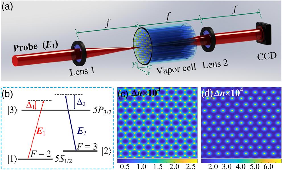
    Fig. 1. Experimental schemes. (a) Illustrative picture of the experimental setup. The focus lengths of the two lenses are both f=150  mm. (b) The three-level Rb85 atomic configuration excited by the probe field E1 and the hexagonal coupling field E2. (c) and (d) Calculated spatial distribution of refractive index for Δ1=80  MHz (c) and Δ1=190  MHz (d) with Δ2=100  MHz, resulting in honeycomb and hexagonal lattices, respectively.
    Momentum space vortex generation in the honeycomb lattice with the two-photon detuning being 20 MHz. (a) Experimentally measured momentum space image interference with the reference beam. The dislocations in fringes correspond to the vortices (marked by white circles). (b) The corresponding phase pattern extracted from the interference image. Black arrows show the rotation direction.
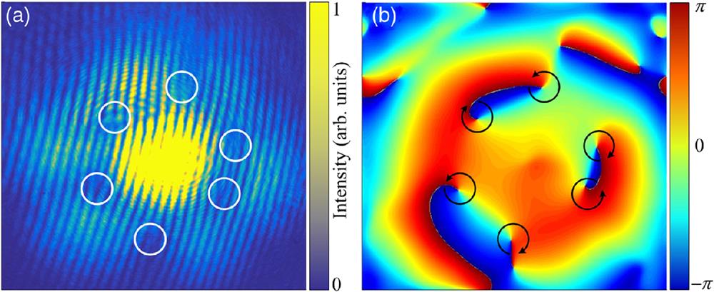
    Fig. 2. Momentum space vortex generation in the honeycomb lattice with the two-photon detuning being 20 MHz. (a) Experimentally measured momentum space image interference with the reference beam. The dislocations in fringes correspond to the vortices (marked by white circles). (b) The corresponding phase pattern extracted from the interference image. Black arrows show the rotation direction.
    Numerical solution of the Schrödinger equation showing wave packet expansion in photonic graphene starting from the excitation of a single site. (a) The probability distribution in real space. (b) The probability distribution in momentum space. (c) The reciprocal space phase image of the WF corresponding to panel (b). The left and right vortices are marked with blue and red circles, respectively. (d) The reciprocal space WF interference with a plane wave. Green circles indicate the Dirac points. The snapshot shows that the WF has the C3v symmetry. Panels (e) and (f) show the results of tight-binding calculation and correspond to panels (a) and (d), respectively.
    Fig. 3. Numerical solution of the Schrödinger equation showing wave packet expansion in photonic graphene starting from the excitation of a single site. (a) The probability distribution in real space. (b) The probability distribution in momentum space. (c) The reciprocal space phase image of the WF corresponding to panel (b). The left and right vortices are marked with blue and red circles, respectively. (d) The reciprocal space WF interference with a plane wave. Green circles indicate the Dirac points. The snapshot shows that the WF has the C3v symmetry. Panels (e) and (f) show the results of tight-binding calculation and correspond to panels (a) and (d), respectively.
    Numerical solution of the Schrödinger equation showing wave packet expansion in photonic honeycomb and hexagonal lattices with various symmetries of the WFs. (a), (b) Honeycomb lattice, excitation of a single “benzene ring” (C6v): real space probability (a) and momentum space phase (b). (c), (d) The same for a honeycomb lattice, excitation between two sites (C2v symmetry). (e), (f) The same for a topologically trivial hexagonal lattice with C2v-excitation.
    Fig. 4. Numerical solution of the Schrödinger equation showing wave packet expansion in photonic honeycomb and hexagonal lattices with various symmetries of the WFs. (a), (b) Honeycomb lattice, excitation of a single “benzene ring” (C6v): real space probability (a) and momentum space phase (b). (c), (d) The same for a honeycomb lattice, excitation between two sites (C2v symmetry). (e), (f) The same for a topologically trivial hexagonal lattice with C2v-excitation.
    Phase patterns in momentum space for alternative symmetries and lattices. Panels (a) and (b) demonstrate absence of vortices for the case of C6v symmetry signal in honeycomb lattice. The momentum space interference image shown in panel (a) contains no fork dislocations in fringe pattern and the extracted phase shown in panel (b) also demonstrates no vortex-like phase defects. Panels (c) and (d) show the interference pattern and extracted phase, respectively, for the C2v symmetry signal realized in the honeycomb lattice by excitation between two sites. Panels (e) and (f) are for the interference pattern and extracted phase, respectively, in the case of the C2v symmetry in hexagonal lattice realized experimentally by setting the two-photon detuning −90 MHz.
    Fig. 5. Phase patterns in momentum space for alternative symmetries and lattices. Panels (a) and (b) demonstrate absence of vortices for the case of C6v symmetry signal in honeycomb lattice. The momentum space interference image shown in panel (a) contains no fork dislocations in fringe pattern and the extracted phase shown in panel (b) also demonstrates no vortex-like phase defects. Panels (c) and (d) show the interference pattern and extracted phase, respectively, for the C2v symmetry signal realized in the honeycomb lattice by excitation between two sites. Panels (e) and (f) are for the interference pattern and extracted phase, respectively, in the case of the C2v symmetry in hexagonal lattice realized experimentally by setting the two-photon detuning 90  MHz.
    Feng Li, Sergei V. Koniakhin, Anton V. Nalitov, Evgeniia Cherotchenko, Dmitry D. Solnyshkov, Guillaume Malpuech, Min Xiao, Yanpeng Zhang, Zhaoyang Zhang. Simultaneous creation of multiple vortex-antivortex pairs in momentum space in photonic lattices[J]. Advanced Photonics, 2023, 5(6): 066007
    Download Citation