H. Ahmad, H. Hassan, R. Safaei, K. Thambiratnam, I. S. Amiri. Q-switched fiber laser using carbon platinum saturable absorber on side-polished fiber[J]. Chinese Optics Letters, 2017, 15(9): 090601
Copy Citation Text
A 1550 nm -switched fiber laser using a carbon platinum saturable absorber deposited on side-polished fiber (SPF) is proposed and demonstrated. The SPF is approximately 2 mm with a polarization-dependent loss (PDL) of 0.4 dB and an insertion loss of 2.5 dB. A stable -switched output spectrum is obtained at 1559.34 nm with a peak power of , a pulse width of 1.02 μs, pulse energy of 5.8 nJ, average output power of 0.76 mW, and a repetition rate of 131.6 kHz taken at a pump power of 230.0 mW. A signal-to-noise ratio of 49.62 dB indicates that the -switched pulse is highly stable.
Fiber lasers capable of generating passive -switched outputs have become the focus of significant research efforts for applications requiring short and powerful pulses[1–4]. In obtaining these pulses, the saturable absorber (SA) has come to play a crucial role, and has been at the forefront of the research and development of passively -switched fiber lasers[5] for a multitude of applications ranging from optical time-domain reflectometery to material processing[6] and remote sensing[7]. Passively -switched fiber lasers are highly desirable as they are able to generate short pulsed outputs in a compact form factor and at a relatively low cost[8,9].
In this work, a -switched erbium-doped fiber laser (EDFL) using carbon platinum (CPt) deposited on a side-polished fiber (SPF) as an SA is proposed and demonstrated. CPt is a relatively new material to be employed as an SA, and can be combined with the SPF, which acts as a highly effective host platform, allowing significant interaction between the light propagating through the SPF and the SA material coating it[10–12]. The SPF structure allows for high sensitivity, and EDFLs have already seen significant application as sensors and other crucial optics[13,14]. The SPF in this work is formed by a simple technique that involves the polishing of a standard single-mode fiber (SMF) until the SPF is formed[15] and allows for the development of a compact SA for passively pulsed fiber lasers[16–19].
The CPt-based SA is fabricated by first mixing chloroplatinic acid hexahydrate () with powdered activated carbon (PAC). Both compounds were obtained from Sigma-Aldrich. The resulting solution is made to undergo ultrasound sonification for a period of about 30 min after which approximately 40 mL of formic acid (HCOOH), which is also obtained from Merck, is added to the solution. The solution is then refluxed at a temperature of 90°C for a period of 6 h, before the temperature is reduced to about 60°C. At this point, the agents and solvents that have not reacted with the solution are removed using the following chemical reaction[1]:
Sign up for Chinese Optics Letters TOC. Get the latest issue of Chinese Optics Letters delivered right to you!Sign up now
The resulting CPt solution is now allowed to dry overnight at room temperature, after which it is dispersed by sonification for about 30 min using a water:ethanol mixture at a ratio of . The mixture is then washed with deionized water and allowed to dry for about 2 h at a constant temperature of 70°C for CPt powder.
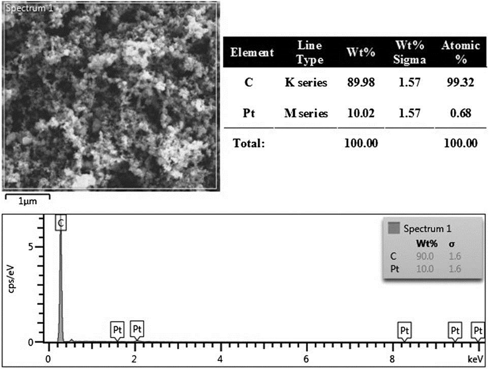
The obtained CPt powder is analyzed for its morphology and elemental composition using an EG Quanta 450 field emission scanning microscope coupled with an EDS Oxford energy-dispersive spectrometer (FESEM-EDS), as given in Fig. 1. The FESEM micrograph clearly shows the formation of CPt microclusters, which themselves group together to form larger clusters. The average microcluster size is about 1/20th of a micrometer, or about 50 nm in diameter, while the larger clusters can be between 200 and 300 μm in size. The CPt nanoparticles can be seen to be relatively well distributed.
Figure 1.FESEM and EDS analysis of the synthesized CPt.
The EDS analysis of the synthesized CPt nanoparticles is also given in Fig. 1, and clearly shows that only the C and Pt elements are present, with concentrations of 90.0 and 10.0 wt %, respectively. This gives a concentration ratio of about for carbon to platinum, and confirms the absence of other elements in the synthesized CPt compound.
The nonlinear optical absorption characteristics of the CPt-based SA are obtained using the twin detector technique. In this technique a fiber laser operating at a central wavelength of 1560 nm with a mode-locked output at a pulse width and repetition rate of 0.70 ps and 27.93 MHz, respectively is used as a source signal for the measurement. The power of the source signal is controlled using a low-dispersion amplifier and a variable optical attenuator, and then split into two equal portions using a 3 dB coupler. One output is connected directly to an optical power meter (OPM), while the other output is connected to the CPt-based SA before being connected to another OPM. The modulation depth and saturation intensity is then computed using where is absorption, is intensity, is saturable absorption, is nonsaturable absorption, and is saturation intensity. Figure 2 provides the absorption of the SA against the power density. The modulation depth and saturation intensity was computed at 0.6% and , respectively, as shown in Fig. 2. While these values are low when as compared to those obtained by Chen et al., ranging from 10.74 to [20,21], it must be noted that these values are obtained for materials such as tungsten disulfide and black phosphorous, which are known to be very active optically. SAs based on metals such as Ag and Zn have much lower saturation intensities and modulation depths, amounting to only 0.54 and and 31.6% and 3.5%, respectively[22,23]. This variation could be due the different fabrication and preparation techniques of the SA, which contributes to the quality of the SA and also the absorption of the edge states in the bandgap[24,25]. However, the value of the saturation intensity in this work is lower than commonly reported values, which could be advantageous for achieving a pulsed fiber laser output[26].
The CPt-based SA itself can be easily fabricated by simply dropping approximately 25 μL of the CPt solution onto the polished part of the SPF using a micropipette and allowing it to dry in air. The resulting fiber with the CPt coating now constitutes the SA, which is then carefully integrated into a laser cavity to generate a -switched output.
For the purpose of this work, a 2 mm long SPF is fabricated. A custom technique was developed to fabricate the SPF, which can produce a very high-quality SPF through a very inexpensive and simple approach. In addition, the proposed technique still allows the user to retain significant control over the dimensions and other parameters of the SPF. The SPF fabrication assembly is given in Fig. 3. In this setup, two Newport M-562-D optical alignment stages and Newport 561-FH fiber holders are used to grip the fiber that will be tapered tightly. The fiber holders are placed approximately 5.2 cm from each other, and another Newport M-562-D optical alignment stage is placed exactly in the middle, on top of which a 3.5 V direct current (DC) motor is secured. The motor has a maximum speed efficiency of 11442 rpm and torque of , with a disk approximately 2.5 cm in diameter attached to the shaft of the motor. Silicon carbide paper with a grit size of 1000 is wrapped around the wheel, thus forming the polishing wheel.
Figure 3.Setup of the polishing assembly for SPF fabrication.
In order to monitor the fabrication process, a 1550 nm test signal at a power of 7 dBm is launched from a tunable laser source (TLS) into one end of the SMF-28 while a Thorlabs OPM is placed at the other end. The ‘leakage’ of light at the polished part of the fiber, as shown in Fig. 4, confirms that the core is now exposed. The overall fabrication process takes no more than 20 min. For this work, two SPFs are fabricated using the same technique. One SPF is used for subsequent experiments, while the other SPF is broken so that the cross section of the polished part can be measured. The unbroken SPF is used to form the CPt-based SA, as described earlier in this work. Figures 5(a) and 5(b) both show the physical dimensions of the fabricated SPF. The cross section of the SPF’s polished area is given in Fig. 5(a). From this figure, it can be seen that the diameter of the SMF has been reduced from its initial value of 125.5 μm to about 66.5 μm after 20 min of polishing. This is a reduction of the thickness of the SMF-28 by about 47% and about 0.8 μm of the core is removed during the polishing process. Figure 5(b), on the other hand, shows the side view of the polished fiber. It can be seen from the figure that the polished region is approximately 2.0 mm long, while the exposed core is approximately 1.0 mm long. The curved structure of the polished section is a result of the polishing process. The insertion loss and polarization dependent loss (PDL) of the SPF is measured to be 2.5 dB and 0.4 dB, respectively.
Figure 4.Visible red light ‘leaking’ from the SMF-28 at the polished part, providing visual indication that the core has been exposed.
The proposed cavity uses a 1480 nm laser diode (LD) as the pump signal source in a backward pumping configuration, and is connected to the 1480 nm port of a 1480/1550 nm wavelength division multiplexing (WDM). The common port of the WDM is connected to a 3 m long Fibercore M-12 Metrogain erbium-doped fiber (EDF), which serves as the active gain medium in this setup. The EDF has an absorption coefficient of 11.3 dB/m at 979 nm, as well as a mode field diameter and numerical aperture of 6.6 μm and 0.21, respectively. The 1550 nm port of the WDM, on the other hand, is connected to the CPt-based SA, and its output is in turn connected to a 95:5 optical coupler, which is used to extract a portion of the signal propagating in the cavity for further analysis through the 5% port. The 95% port of the coupler is connected to an optical isolator, which ensures the unidirectional propagation of the signal through the cavity, and the isolator is in turn connected to the EDF, thus completing the optical circuit. The output from the 5% port of the optical coupler is now divided into two equal portions using a coupler, with one portion being used to characterize the optical parameters of the generated outputs, and the other used to analyze the pulse characteristics.
The lasing spectrum of the proposed -switched laser is obtained using a Yokogawa AQ6370B optical spectrum analyzer (OSA) with a resolution of 0.02 nm. Lasing is observed to occur at a pump power of 120.0 mW, while -switching begins at a pump power of 135.5 mW. Figure 6 shows the superimposed spectrum of the lasing wavelength in both the continuous wave (CW) and -switching regimes. Figure 7 shows an ordinary optical output spectrum of the -switched pulse at a pump power of 135.5 mW, which has a central wavelength at approximately 1559.34 nm and a 3-dB bandwidth of 1.2 nm.
Figure 6.(Color online) Output spectrum with and without the CPt SA.
Figure 7(a) provides the pulse train generated by the -switched fiber laser. The pulse train can be seen to have a repetition rate of 99.6 kHz at a pump power of 179.6 mW. The pulses are spaced 0.1 μs apart, with each individual pulse having a full width at half-maximum (FWHM) of 1.5 μs. This is given in Fig. 7(b). It can also be seen from the figure that the pulse is smooth, with a clean Sech2-shape and no Kelly’s sidebands observed, thereby eliminating the possibility of a mode-locked pulse.
When observed against a rising pump power, the repetition rate, pulse width, pulse energy and average output power of the output generated by the proposed system corresponds to that of a typical -switched laser[27]. For the proposed system, the repetition rate is approximately 67.4 kHz at a pump power of 135.5 mW, with a pulse width, pulse energy, and average output power of 2.3 μs, 5.2 nJ, and 0.35 mW, respectively, at the same pump power. As the pump power increases, reaching a value of 230.0 mW, the pulse energy, average output power, and repetition rate are all seen to increase in an almost linear fashion to 5.8 nJ, 0.76 mW, and 131.6 kHz, respectively. The pulse width, on the other hand, decreases, reaching a minimum value of 1.02 μs at the maximum pump power. Although the pulse width is typically expected to decrease exponentially as the pump power rises, the gradual linear decrease observed in this work is attributed to the SA’s saturation limit being much higher than that can be reached by the system. It is expected that should the pump power be increased further, the pulse width would eventually plateau out before reaching its saturation value and remain unchanged even if the pump power continues to be increased.
The response of the repetition rate and pulse width against the pump power is given in Fig. 8(a), while the response of the pulse energy and average output power against the pump power is given in Fig. 8(b). The relatively high repetition rate can be achieved due to the low saturable optical intensity of the SA[28,29]. The repetition rate achieved in this work is substantially higher than that typically observed, ranging from a few kHz to 100 kHz[30], and it is also possible to achieve higher repetition rates should higher pump powers be available.
Figure 8.(Color online) (a) Repetition rate and pulse width against the pump power, and (b) the average output power and pulse energy against the pump power.
Figure 9 provides the radio-frequency (RF) scan of the generated pulses. From Fig. 9, it can be observed that a single fundamental frequency is obtained, corresponding to a repetition rate of 131.56 kHz taken at a pump power of 230 mW. A signal-to-noise ratio (SNR) of 49.62 dB is observed, indicating a highly stable pulse. The inset of the figure shows the RF harmonics taken from a bigger span of 100 kHz at pump power of 230 mW.
Figure 9.RF optical spectrum and inset showing the wideband RF spectrum.
An SPF deposited with CPt saturable is demonstrated to get a -switching pulse. The SPF is homemade by using a fabrication process that is very effective and affordable compared to commercial SPF. A micropipette is used to drop the CPt on the surface of the SPF. A rigid -switched pulse at a central wavelength of 1559.34 nm and SNR of 49.62 dB is generated by integrating the SPF into the proposed laser resonator.
The maximum repetition rate is 131.6 kHz, having an average output power of 0.76 mW with a pulse energy of 5.8 nJ and a pulse width of 1.02 μs taken at a pump power of 230.0 mW. This result demonstrates that this homemade SPF and the CPt SA are capable of producing a -switched fiber laser, which will be very significant in many fiber laser and sensor applications, especially those that need cheap, compact, and effective optical equipment.
[30] R. I. Álvarez-Tamayo, Mukul Chandra Paul, M. Durán-Sánchez, O. Pottiez, B. Ibarra-Escamilla, E. A. Kuzin, M. Espinosa-Martínez. Active Q-switched fiber lasers with single and dual-wavelength operation. Fiber Laser(2016).
H. Ahmad, H. Hassan, R. Safaei, K. Thambiratnam, I. S. Amiri. Q-switched fiber laser using carbon platinum saturable absorber on side-polished fiber[J]. Chinese Optics Letters, 2017, 15(9): 090601