Vector beams with spatially variant polarization have attracted much attention in recent years, with potential applications in both classical optics and quantum optics. In this work, we study a polarization selection of spatial intensity distribution by utilizing a hybridly polarized beam as a coupling beam and a circularly polarized beam as a probe beam in atom vapor. We experimentally observe that the spatial intensity distribution of the probe beam after passing through atoms can be modulated by the hybridly polarized beam due to the optical pumping effect. Then, the information loaded in the probe beam can be designedly filtrated by an atomic system with a high extinction ratio. A detailed process of the optical pumping effect in our configurations and the corresponding absorption spectra are presented to interpret our experimental results, which can be used for the spatial optical information locally extracted based on an atomic system, which has potential applications in quantum communication and computation.
In recent years, vector beams with spatially nonuniform polarization distribution have attracted much interest [1] for their potential applications in optical micromanipulation [2] and trapping [3–6], high-resolution imaging [7], nano-optics [8], and quantum communication [9–12]. Usually, the vector beams can be generated by two means, i.e., intracavity generation technique [13–17] and extracavity generation method, while the extracavity method, due to its convenience [18–21], has been adopted by many researchers. Using inhomogeneous anisotropic plates, so called Q-plates, is a flexible and efficient way to produce a vector beam by the extracavity [22–25]. Note that the polarization status of an incident beam determines the generated mode of a vector beam. By adjusting the polarization direction of a linearly polarized beam related to the axis of Q-plates, one can obtain radially or azimuthally polarized vector beams [26]. In general, the preponderant character of vector beams is a spatial varied distribution of polarization, which can also, by using few wave plates (such as a half-wave plate or quarter-wave plate), be converted to different vector beams [27]. When a radially polarized beam (linear polarization aligned in the radial direction) illuminates a quarter-wave plate (QWP), the polarization distribution would be a hybridly polarized beam, which contains varied distribution of polarization such as linear, elliptical, and circular polarizations [28].
Compared with the vector beam manipulation with linear optical devices, an atomic ensemble also provides a fast and controllable platform for light manipulation. Thus far, vector beams have been widely used for exploring the interaction between the light and atoms. Using cold atoms, the quantum memory of vector beams in a multiple of degrees of freedom has been realized [29], and phase-dependent dark states, which in turn lead to phase-dependent electromagnetically induced transparency (EIT), have been generated [30]. Using vector beams to realize polarization shaping for preventing beam fragmentation in nonlinear propagation [31] and to achieve the spatially dependent atoms’ spin [27] has also been observed. More recently, manipulating the spatial intensity and polarization distribution of vector beams by an atomic system as a tunable analyzer has been explored [32].
Obviously, the spatially nonuniform polarization in an atomic ensemble caused by vector beams provides a feasible way to manipulate light propagation properties. In this paper, we use a counterpropagated pump–probe configuration to study how a hybridly polarized beam affects the propagation behavior of a fixed polarized light, specifically, circularly polarized light. A polarization selection transparency has been observed and used for the spatial information extraction. Our counterpropagated pump–probe configuration is similar to a common saturated absorption spectroscopy (SAS) configuration. SAS is a technique for learning sub-Doppler hyperfine resonance lines of a Doppler broadened atomic sample. It can be widely used in locking laser frequency and spectrum analysis in atomic and molecular physics [33–35]. There have been a large number of experimental and theoretical studies of SAS [36–40]. But most research is mainly focused on the spectrum for a probe beam with a single polarization state.
Sign up for Photonics Research TOC. Get the latest issue of Photonics Research delivered right to you!Sign up now
In our work, we use a hybridly polarized vector beam as a coupling beam to polarize the atoms; then, a fixed circularly polarized beam counterpropagates with the coupling beam. We find the spatial intensity distribution of the probe beam can be modulated by the hybridly polarized beam due to the optical pumping effect. We thereby utilize these properties to designedly filtrate the spatial information loaded in the probe beam, and the high extinction ratio can be obtained. A detailed process of the optical pumping effect under different light polarization configurations and the corresponding absorption spectra are presented to interpret our experimental results.
The outline of this paper is as follows. In Section 2, we describe our experimental scheme and results and apply the polarization selection transparency for the spatial distribution information extraction. In Section 3, we present a detail discussion on the principle of polarization selection transparency in our work. Several polarized light combinations are used in our pump–probe configuration to interpret our results. The conclusion follows in the final section.
2. EXPERIMENTS AND RESULTS
A. Experimental Setup and Measurement of Stokes Parameters
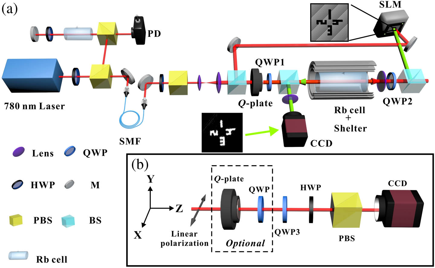
An experimental diagram is shown in Fig. 1(a). A 780 nm external cavity diode laser (Toptica DL pro) is used for coupling and probe beams. The laser beam is divided into two orthogonally polarized beams using a polarization beam splitter (PBS), where 1% of total power of the laser beam is reflected for the saturated absorption spectroscopy, while the remaining 99% is transmitted and collected by a single-mode fiber (SMF) to improve the spatial mode. Then, a half-wave plate (HWP) and a PBS are placed after the SMF to adjust the light intensity of the horizontally linearly polarized beam in the experiment. After the beam size is expanded to 3 mm by a telescope, we generate the coupling and probe beams by a beam splitter (BS).
The coupling beam passes through a Q-plate and QWP1 to convert a linearly polarized beam to a hybrid polarization through the radially polarized states, while the probe beam after passing a liquid crystal spatial light modulator (SLM) changes to a circularly polarized beam with a QWP2 and counterpropagates with the coupling beam. In order to ensure two beams overlap more effectively in the Rb cell and overcome the diffraction generated from SLM, we use a pair of lenses to make up a system to obtain a well-defined profile of the probe. The illustrations in Fig. 1(a) show the phase profile encoded on the SLM and the information distribution of probe beam. Here, we select the different numbers in various spatial distributions as the probe beam. The intensities of coupling and probe beams are fixed at 2 mW and 40 μW approximately by using neutral density filters (not shown in figure), respectively. The Rb cell has a length of 50 mm filled with enriched gas. A three-layer μ-metal magnetic shield is used to isolate the cell from ambient magnetic fields. The temperature of the cell is set to 60°C with a temperature controller (not shown in the figure). After passing through the cell, the probe beam is detected by a charge-coupled device camera (CCD). In our experiment, we lock the laser in one crossover signal ( to and to , line) of .
To verify the polarization states we used in the experiment, we compose the Stokes parameters measurement setup with a combination of QWP, HWP, PBS, and CCD, as shown in Fig. 1(b). A neutral density filter (not shown in Fig. 1) is used before the CCD to avoid overexposure. The Stokes parameters are a set of indices (, , , and ), which represent the polarization of light [41–44]. When the optical fast axes of QWP3 and HWP make up the following combinations, we can obtain the corresponding Stokes parameters of the light: where stands for the intensity when the optical fast axis of QWP3 is and of HWP is with respect to the horizontal direction.
The normalized Stokes parameters of each beam are shown in Fig. 2. The first row represents a circularly polarized state carried by a probe beam (transmitting a horizontally linearly polarized beam through a QWP with a fast axis oriented at 45°, with respect to the horizontal direction); thus, the and , while the equals the total intensity of the light (). The second row stands for the radially polarized beam with axial symmetry after the control beam passing through the Q-plates. Both and show a four-lobe pattern but with different directions, while because the light beam is essentially a linear polarization, and no circularly polarized component exists. The last row is the final hybridly polarization state for the coupling beam generated by transmitting a radially polarized beam through QWP1 (the optical fast axis is oriented at 0° with respect to the horizontal direction). means there is no linear polarization in 45° direction with respect to the horizontal direction; and show a four-lobe pattern with different orientations and represent the linear polarization and circular polarization in the corresponding position. The hybridly polarized coupling beam will lead atoms spatially varied polarization; thereby, the absorption of a circularly polarized probe beam strongly relies on the spatially polarized distribution of the coupling beam.
Figure 2.Experimental results of Stokes parameters measurement. Top to bottom row: circularly polarized beam, radially polarized beam, and hybridly polarized beam, respectively. Arrowed lines inside the first column figures indicate the polarization states.
The experimental results of the hybridly polarized coupling beam with a single circularly polarized probe beam are shown in Fig. 3. Here, the SLM acts as a reflective mirror, and no spatial information is loaded. We can see a two-lobe pattern after the probe beam passes through atoms [27]. The similar propagation properties can also be realized in atomic ensembles by utilizing the Hermite–Gaussian TE (TM) dipole mode [45] or Laguerre–Gaussian vortex mode [46] via the multiwave mixing process. And the maximum intensity of probe beam corresponds to the reversely circularly polarized state of the coupling beam, while the absorption occurs at the same circularly polarized position. The spatial distributed orientation of the two-lobe pattern can be controlled by rotating the QWP1 as rotation of the hybridly polarized coupling beam shown in Figs. 3(a)–3(d). We choose Fig. 3(a) and obtain the azimuthal intensity profile shown in Fig. 3(j), which is a sinusoidal tendency. The azimuthal variation is calculated from 0° to 180°, and the angular direction is defined in Fig. 3(i). We use approximately 10 points on each line, with a distance between each point of 0.15 mm. Each point is box-averaged using approximately 5 pixel × 5 pixel, and one pixel corresponds to 5.8 μm. The results in Fig. 3(j) indicate that a coupling beam acts as a selector with a high extinction ratio, which can be used to extract the spatial information carried by the probe beam.
Figure 3.Experimental results of polarization selection transparency. (a)–(d) Two-lobe pattern exits at the position where the polarization of the coupling beam is orthogonal to the probe beam. (e)–(h) Spatial information after filtrating. The fast axis rotation angles of QWP1 are 0°, 45°, 90°, and 135°, with respect to the horizontal direction. Yellow dashed line in figure corresponds with the fast axis direction of QWP1. (i) Diagram for selecting azimuthal angle. (j) Normalized intensity of azimuthal distribution.
Now we load the phase profile [illustrated in Fig. 1(a)] on the SLM. Here, we choose four different numbers oriented in two perpendicular directions as the information we want to filter. The same as the intensity lobes’ appearance, the information loaded in the probe beam can be designedly filtrated by an atomic system with a high extinction ratio, as shown in Figs. 3(e)–3(h). Therefore, we could use this configuration to engineer information extraction via polarization selection transparency based on atomic ensembles.
3. DISCUSSION
A. Principle of Polarization Selection Transparency
Here, we qualitatively explain the principle of polarization selection transparency by optical pumping effect in our works. Note our above results are more related to the circularly polarized light. Thus, we define that all circularly polarized beams in this work are along the direction of beam propagation. In a conventional SAS configuration, a linearly polarized probe beam (weak) propagates through the Rb cell along the axis; meanwhile, another linearly polarized coupling beam (orthogonally polarized to the probe beam with much stronger intensity) counterpropagates and overlaps with the probe beam [36]. In the absorption profile of the probe beam, the velocity-selective signal is observed as the laser frequency is scanned through a resonance line of the atoms. Using the linearly polarized beam for the SAS can help us to understand the hyperfine energy levels and the crossover resonance between the hyperfine energy levels. The population of the corresponding energy level can be influenced by a strong coupling beam; hence, the probe could transmit without absorption through the atoms. If we preset the probe beam as a circularly polarized beam and change the polarization states of a coupling beam between left and right circular polarization states, the transmission characteristics of the probe will also vary because of the optical pumping effect [40,47,48] or coherent effect between atomic energy levels [49,50].
Figure 4(a) shows an energy level diagram for the line of atoms used in our experiment. The linearly polarized beam couples the , while the circularly polarized beam couples the . In Fig. 4(b), the strong coupling beam with optically pumps atoms to the ground energy level, so other ground energy levels are empty. When a weak probe beam with interacts with atoms, it can lead to intense absorption for a probe beam because atoms actually see the opposite circular polarization from the probe. The situation in Fig. 4(c) is different from that in Fig. 4(b), the strong coupling beam with and the weak probe beam with couple the same energy level; hence, the probe beam transmits without absorption. Figures 4(d) and 4(e) are similar situations when the probe beam is and coupling beam with or .
Figure 4.(a) Hyperfine-energy level diagram of the line of atoms. Degenerate energy level diagram for to and in line of atoms on the right side. Red: coupling beam; green: probe beam. (b) for probe and for coupling. (c) for probe and for coupling. (d) for probe and for coupling. (e) for probe and for coupling.
Now we proceed with the experiment to verify our qualitatively interpretation. The experimental setup is shown in Fig. 5(a). The coupling beam (red) is expanded to a diameter of 3 mm, and the counterpropagating probe beam (green) is 2 mm. The intensities of coupling and probe beams are fixed at 2 mW and 40 μW approximately by using neutral density filters (not shown in the figure), respectively. The coupling beam and counterpropagating probe beam are collinear and overlapped in the Rb cell. Meanwhile, the polarization states of beams are adjusted by QWP1 and QWP2 for different rotation angles. The transmitted probe beam intensity is monitored by a photodetector.
Figure 5.Experimental setup and results of spectrum measurement. (a) Diagram of experiment. (b) Polarization state of probe beam is . (c) Polarization state of probe beam is . Different color curves represent the different coupling beam polarization states. Red (curve): (the fast axis rotation angle of QWP1 corresponding to the horizontal direction); orange: ; green: ; light cyan: 0°; violet: ; blue: ; dark yellow: . (d), (e) Intensity variations corresponding to the laser locked in the against rotation angle in (b) and (c), respectively.
The experimental results are shown in Figs. 5(b)–5(e). First, we scan the laser around the line of the for to energy levels. Figure 5(b) shows typical saturated absorption spectroscopy (upper) and the intensity of transmitted probe beam signals (lower), where the probe beam is against different polarization states of the coupling beam. The stands for the resonance signal, where the coupling and probe beams are tuned at to , and represents the crossover signal when the coupling beam is tuned at to , and the probe beam is tuned at to or vice versa. As shown in Fig. 5(b), the transmitted signal corresponding to the crossover resonance decreases by changing the rotation angle of QWP1, and the spectrum curves turn to valley from peak [51]. The transmitted peak occurs at the opposite circular polarization for coupling and probe beams because the strong coupling beam pumps the atoms into the nonabsorbing state for a probe beam, as described in Fig. 4(c). On the contrary, when a counterpropagating coupling beam and probe beam have the same circular polarization, the intense coupling beam accumulates atoms in the most absorption state examined by the probe beam; thus, we obtain a valley in the spectrum corresponding to Fig. 4(b). Figure 5(c) shows the reversed results when the probe beam is .
In order to obtain a specific variation tendency of the intensity against the polarization states of coupling beams, we locked the laser on the transition of atoms as in the above experiment. Figures 5(d) and 5(e) show the normalized intensity of a circular probe beam against the rotation angles of QWP1 as varied polarization states of coupling beams. The rotation angles correspond to the angle between the optical fast axis of QWP1 and the horizontal direction, which give a coupling beam with varied polarization states of linear, elliptical, and circular polarizations. The rotation angle in and corresponds to the opposite circular polarization of a coupling beam. At these two positions, we can either obtain the maximum or minimum intensity transmission, depending on the left or right circular polarization of the probe beam, as shown in Figs. 5(d) and 5(e). The experimental results also show a sinusoidal variation tendency for rotating the QWP1 from to perfectly, as shown in Fig. 3(j). This can be considered as a linearly polarized beam passing through a rotating QWP; thus, we could obtain the sinusoidal intensity variation tendency of a single circular polarization component by an analyzer [41].
Bearing the knowledge that the transmitted spectrum of a circularly polarized probe beam with varied polarization states of coupling beams, by using a hybridly polarized beam with spatially nonuniform polarization distribution, which contains linear, elliptical, and circular polarizations for the coupling beam, we can obtain spatially varying intensity as a combination of different transmitted intensity for a probe beam in an atomic ensemble, as shown as the two-lobe pattern in Fig. 3. From the spectrum, we also realize the polarization selection transparency that could occur in other resonance lines, and the principle is consistent with what we mentioned above.
4. CONCLUSION
In conclusion, we have demonstrated that a hybridly polarized beam can be used to designedly filtrate the spatially distributed information carried by the probe beam in Rb atom vapor. This polarization selection transparency is due to optical pumping under different polarized light. A detailed process of the optical pumping effect in our configurations and the corresponding absorption spectra are presented to interpret our experimental results. The method using the hybridly polarized beam as a selector with high extinction ratio can be applied to quantum information or quantum computation based on atom ensembles.